Centrifugal oil-gas separator and engine applying same

An oil and gas separator, centrifugal technology, applied in the direction of machines/engines, engine components, mechanical equipment, etc., can solve the problems of small scope of application, high production cost, many parts, etc., to reduce production costs, facilitate production, reduce effect of possibility

Pending Publication Date: 2019-04-16
NINGBO LIDA INTELLIGENT CONTROL TECH CO LTD
View PDF9 Cites 0 Cited by
  • Summary
  • Abstract
  • Description
  • Claims
  • Application Information

AI Technical Summary

Problems solved by technology

", but when the displacement is greater than 500CC, the oil in the lower drive chamber will still enter the separation chamber, the scope of application is small, and there are many parts, the production cost is better, and the installation is more troublesome

Method used


Image

  • Centrifugal oil-gas separator and engine applying same
  • Centrifugal oil-gas separator and engine applying same
  • Centrifugal oil-gas separator and engine applying same

Examples


Embodiment 1

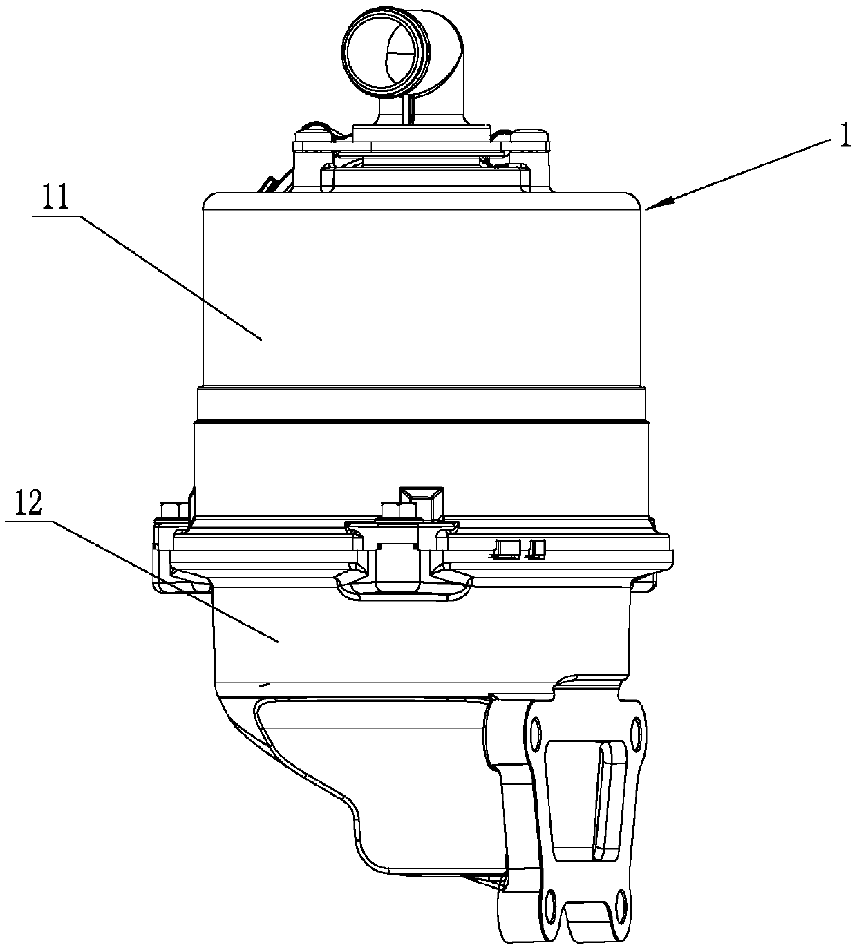
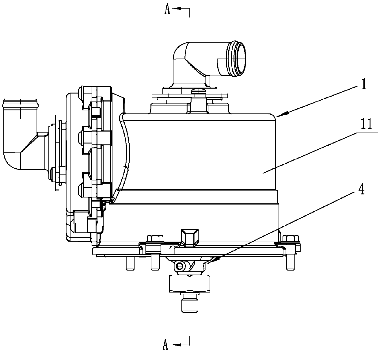
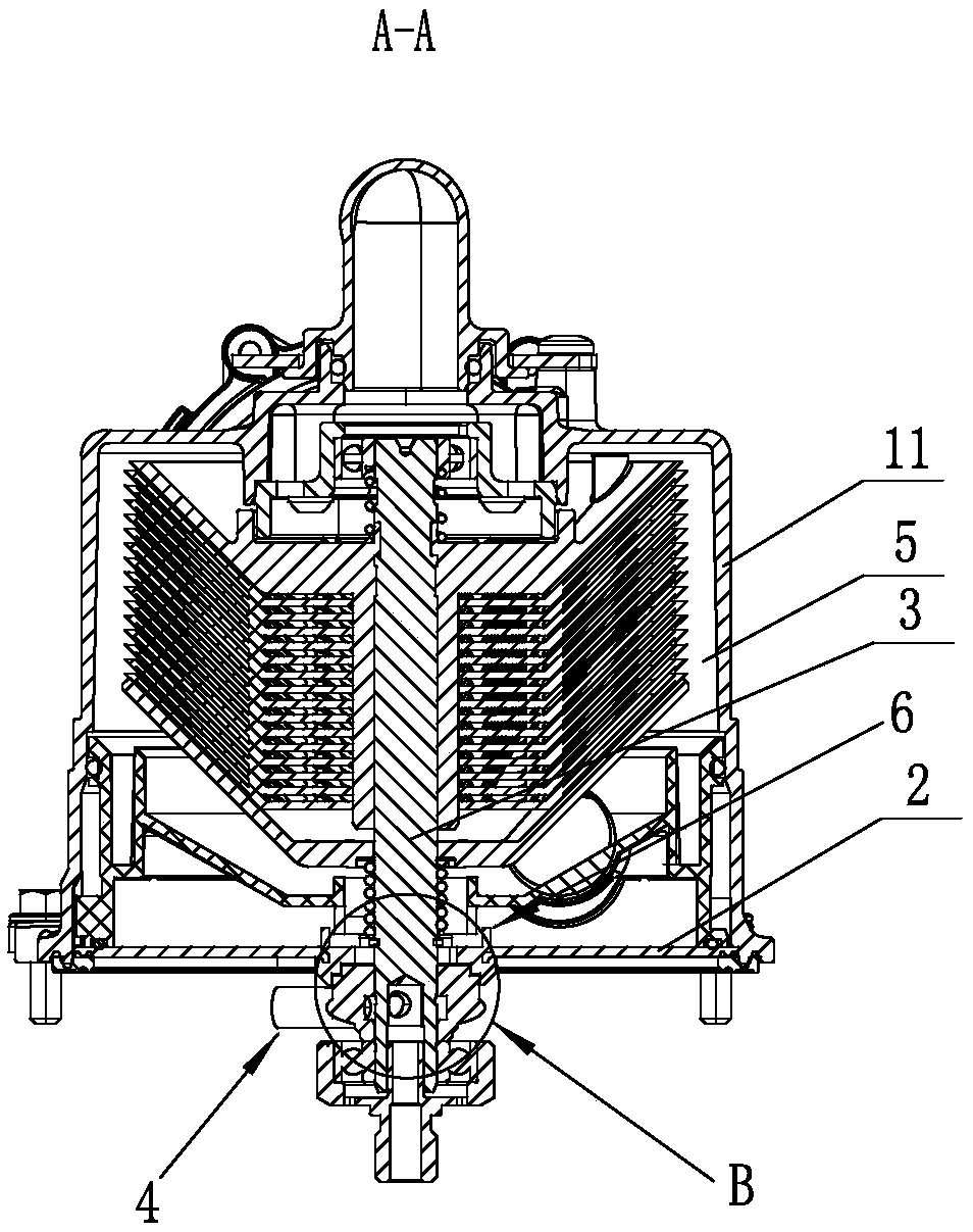
[0028] Such as Figure 1-4 Shown, a kind of centrifugal type oil-gas separator, it comprises housing 1, cavity dividing plate 2, rotating shaft 3 and drive plate 4 (certainly also comprises other components, but because the invention point that does not relate to the invention of the present invention, so in This will not be repeated), the housing 1 is divided into an upper housing 11 and a lower housing 12, the cavity partition 2 is fixed at the position between the upper housing 11 and the lower housing 12, the cavity partition 2 and the upper The inner cavity of the housing 11 forms a separation cavity 5, the cavity partition 2 and the inner cavity of the lower casing 12 form a driving chamber, and the driving disc 4 is located in the driving chamber, and the center of the cavity partition 2 is provided with a communication separation chamber. cavity 5 and the through hole of the driving chamber, and the sleeve 6 is fixedly arranged in the through hole, the upper end of the...

Embodiment 2

[0032]A kind of centrifugal oil-gas separator, it comprises casing 1, cavity dividing plate 2, rotating shaft 3 and drive plate 4 (also comprises other components of course, but because the invention point that does not relate to the invention of the present invention, so no longer here repeat), the housing 1 is divided into an upper housing 11 and a lower housing 12, the cavity partition 2 is fixed at a position between the upper housing 11 and the lower housing 12, the cavity partition 2 and the upper housing 11 The inner cavity of the cavity forms a separation cavity 5, the inner cavity of the cavity partition plate 2 and the lower housing 12 forms a drive chamber, and the drive disc 4 is located in the drive chamber, and the center of the cavity partition plate 2 is provided with a communication separation cavity 5 and The through hole of the drive chamber, and the sleeve 6 is fixedly arranged in the through hole, the upper end of the rotating shaft 3 is rotatably matched w...

Embodiment 3

[0036] Such as Figure 5 Shown, a kind of centrifugal type oil-gas separator, it comprises housing 1, cavity dividing plate 2, rotating shaft 3 and drive plate 4 (certainly also comprises other components, but because the invention point that does not relate to the invention of the present invention, so in This will not be repeated), the housing 1 is divided into an upper housing 11 and a lower housing 12, the cavity partition 2 is fixed at the position between the upper housing 11 and the lower housing 12, the cavity partition 2 and the upper The inner cavity of the housing 11 forms a separation cavity 5, the cavity partition 2 and the inner cavity of the lower casing 12 form a driving chamber, and the driving disc 4 is located in the driving chamber, and the center of the cavity partition 2 is provided with a communication separation chamber. cavity 5 and the through hole of the driving chamber, and the sleeve 6 is fixedly arranged in the through hole, the upper end of the r...


PUM


Abstract

The invention discloses a centrifugal oil-gas separator. The centrifugal oil-gas separator comprises a shell, a cavity partition plate, a rotating shaft and a driving disc, wherein the cavity partition plate and the shell are used for forming a separation cavity in a separated mode, a sleeve pipe is arranged on the cavity partition plate, the lower end of the rotating shaft penetrates through thesleeve and then is connected with the driving disc, and a step-shaped gap seal is arranged between the upper end of the driving disc and the lower end of the sleeve. The centrifugal oil-gas separatorhas the beneficial effects that the step-shaped gap seal is directly adopted, compared with an original maze seal and an original fan and horizontal clearance seal combination, parts are reduced, theproduction is facilitated, the installation is simple and convenient, and the manufacturing cost is saved; and due to the facts that the path of the whole gap seal is long and the structure of the gapseal is a step-shaped structure, oil needs to pass through two upward climbing processes when the oil in a driving chamber enters the gap again, and the horizontal step surface can also play a role in reducing pressure and buffering the incoming oil, so that the oil in the driving chamber is also not prone to entering the separation cavity.

Description

technical field [0001] The invention relates to the technical field of oil-gas separation, in particular to a centrifugal oil-gas separator used for oil-gas separation in a crankcase of a vehicle engine and an engine used therein. Background technique [0002] At present, there are two kinds of sealing structures in the centrifugal oil-gas separator. A kind of prior art publication number is CN101189414A, the name is used for the device (10) that is used for purifying gas while pumping gas to crankcase is disclosed by the device for purifying gas while pumping gas to crankcase, The device (10) comprises: a housing (12) with a separation chamber (14) inside, a rotor structure with a rotor shaft (32) and a centrifugal rotor (39), the rotor shaft (32) is rotatably Mounted in said housing, the centrifugal rotor (39) is located in the separation chamber (14), and - fluid drive means (64) for driving the rotor shaft (32) by means of a drive fluid, said drive means (64) is arrang...

Claims


Application Information

Patent Timeline
Patent Type & Authority Applications(China)
IPC IPC(8): F01M13/04
CPCF01M13/04
Inventor 糜亮陈雨光吕明会冯彬叶勇
Owner NINGBO LIDA INTELLIGENT CONTROL TECH CO LTD
Why Eureka
Try Eureka