Steam line leakage detection system

A leak detection and steam pipeline technology, applied in the field of steam pipeline leak detection system, can solve the problems of boiler safety and stability impact, threat to personnel safety and economic loss, inadequate preventive measures, etc., to prevent flying objects from hurting people and manufacturing costs. Low, wide range of effects

Inactive Publication Date: 2019-04-16
亿利洁能科技(颍上)有限公司
View PDF10 Cites 2 Cited by
  • Summary
  • Abstract
  • Description
  • Claims
  • Application Information

AI Technical Summary

Problems solved by technology

[0002] There are high-temperature and high-pressure boiler pipelines and pressurized gas pipelines in steel mills, aluminum factories, heating and power generation plants. As the pipeline ages, the pipeline will leak due to corrosion and erosion of external gas and dust. After the pipeline leaks, it will directly affect the safety and stability of the boiler, and cause serious damage to the boiler.
[0003] The existing steam pipeline leakage detection system usually uses a computer control system. When a pipeline leak is detected, it is detected by the change of the air pressure, and then an alarm command is issued to remind the maintenance personnel to carry out inspection and maintenance. There will be a certain period of time during the maintenance process. During this period of time, the cracks in the pipeline may increase due to air pressure. If the cracks are too large, the pipeline may burst, which seriously threatens the safety of personnel and causes economic losses. in place

Method used


Image

  • Steam line leakage detection system
  • Steam line leakage detection system
  • Steam line leakage detection system

Examples


Embodiment Construction

[0021] The following will clearly and completely describe the technical solutions in the embodiments of the present invention with reference to the accompanying drawings in the embodiments of the present invention. Obviously, the described embodiments are only some, not all, embodiments of the present invention. Based on the embodiments of the present invention, all other embodiments obtained by persons of ordinary skill in the art without making creative efforts belong to the protection scope of the present invention.

[0022] In the description of the present invention, it should be noted that the terms "center", "upper", "lower", "left", "right", "vertical", "horizontal", "inner", "outer" etc. The indicated orientation or positional relationship is based on the orientation or positional relationship shown in the drawings, and is only for the convenience of describing the present invention and simplifying the description, rather than indicating or implying that the referred d...


PUM


Abstract

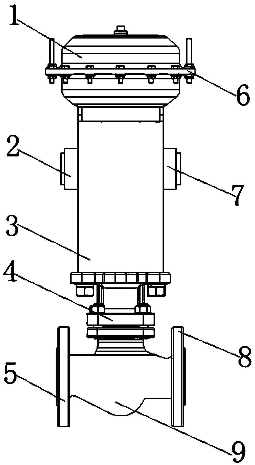
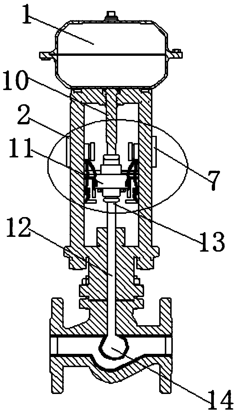
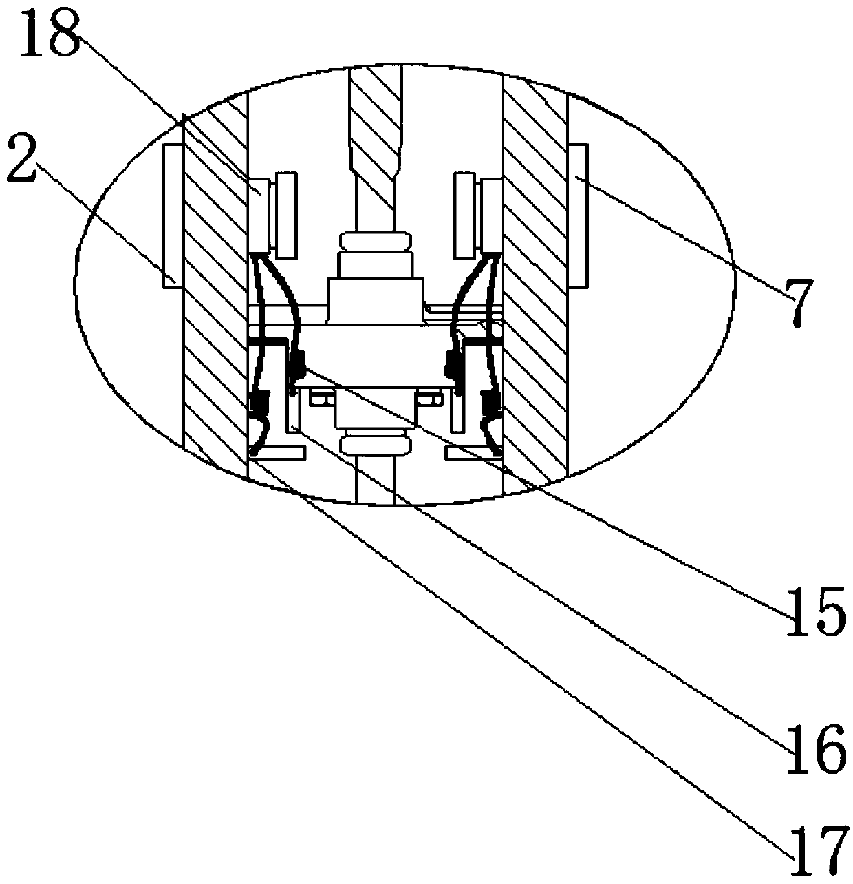
The invention discloses a steam line leakage detection system. The steam line leakage detection system comprises a valve body. An installation opening is connected with the bottom end of the valve body. A fixed base is connected with the bottom end of the installation opening through bolts. Through holes are formed in the two ends of the fixed base. A cavity is formed in the bottom end of the fixed base. A first horn-shaped opening is arranged at the one third position from top to bottom on one side of the valve body in an inlaid manner, and a second horn-shaped opening is arranged at the onethird position from top to bottom on the other side of the valve body. A cylinder bolt is installed on the top of the valve body. The steam line leakage detection system is simple and compact in structure, low in manufacturing cost, safe, reliable, long in service life and wide in application range; the whole detection system is naturally an air valve, and the airtightness of the detection systemis guaranteed; when the air pressure in a steam line is stable, a valve ball is jacked up, two overlap plates get away from each other, and an alarm is not electrified; and when leakage occurs to thesteam line, the air pressure in the steam line is smaller than the intensity of pressure in the air cylinder, the valve ball is pushed out, the two overlap plates are attached to each other to form aloop, and the alarm is electrified to work.

Description

technical field [0001] The invention relates to the field of pipeline leakage detection, in particular to a steam pipeline leakage detection system. Background technique [0002] There are high-temperature and high-pressure boiler pipelines and pressurized gas pipelines in steel mills, aluminum factories, heating and power generation plants. As the pipeline ages, the pipeline will leak due to corrosion and erosion of external gas and dust. Phenomenon, pipeline leakage will directly affect the safety and stability of the boiler, causing serious damage to the boiler. [0003] The existing steam pipeline leakage detection system usually uses a computer control system. When a pipeline leak is detected, it is detected by the change of the air pressure, and then an alarm command is issued to remind the maintenance personnel to carry out inspection and maintenance. There will be a certain period of time during the maintenance process. During this period of time, the cracks in the ...

Claims


Application Information

Patent Timeline
Patent Type & Authority Applications(China)
IPC IPC(8): F17D5/02F17D5/00G01M3/28
CPCF17D5/005F17D5/02G01M3/2815
Inventor 白云飞张永锋
Owner 亿利洁能科技(颍上)有限公司
Why Eureka
Try Eureka