A Design Method for Illumination Optical System with Freeform Surface

A lighting optical system and design method technology, applied in optics, optical components, instruments, etc., can solve the problems of low design efficiency, difficulty, poor stability, etc.

Active Publication Date: 2020-09-15
CHANGCHUN INST OF OPTICS FINE MECHANICS & PHYSICS CHINESE ACAD OF SCI
View PDF4 Cites 1 Cited by
  • Summary
  • Abstract
  • Description
  • Claims
  • Application Information

AI Technical Summary

Problems solved by technology

[0024] The present invention provides a design method for a free-form lighting optical system in order to solve the existing conventional M-A method in the process of designing free-form surface optical systems.

Method used


Image

  • A Design Method for Illumination Optical System with Freeform Surface
  • A Design Method for Illumination Optical System with Freeform Surface
  • A Design Method for Illumination Optical System with Freeform Surface

Examples


specific Embodiment approach 1

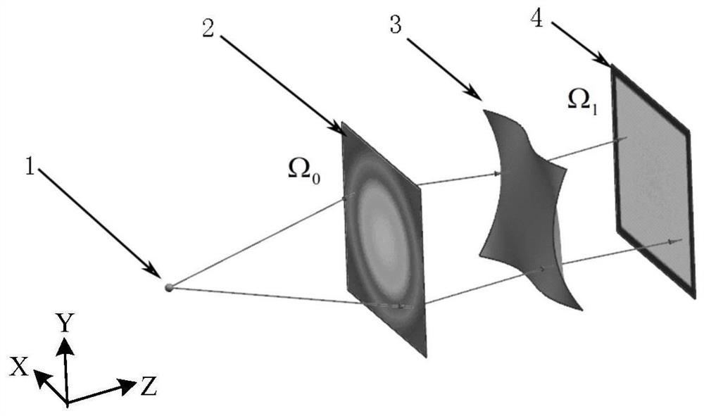
[0049] Specific implementation mode 1. Combination Figure 1 to Figure 6 Describe this embodiment, a design method of a free-form surface illumination optical system, the specific process is:

[0050] 1. According to figure 1 The overall system layout shown, using a new coordinate mapping relationship to replace formula (1), the expression is:

[0051] tx=ρ’ u ,ty=ρ’ v (6)

[0052] In the formula: ρ' is the virtual free-form surface parameter, ρ' u ,ρ' v represent the first-order partial derivatives of ρ' to u and v, respectively;

[0053] (2) According to the coordinate mapping relationship provided by equation (6), combined with the energy conservation equation (2), a new equation can be obtained

[0054] I(u,v)=L(tx,ty)|J'(tx,ty)| (7)

[0055] In the formula: J'(tx,ty)-formula (6) mapping relationship tx=ρ' u ,ty=ρ' v The Jacobin matrix.

[0056] (3) The virtual free-form surface needs to satisfy the boundary conditions while satisfying the energy equation of fo...

specific Embodiment approach 2

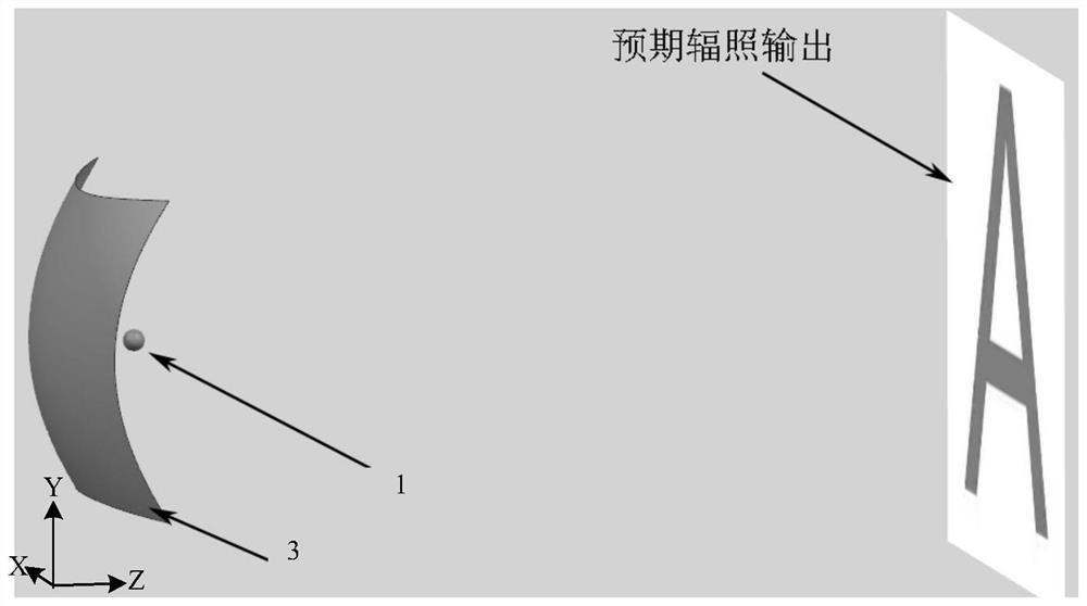
[0062] Specific embodiment 2. Combination Figure 2 to Figure 6 Describe this embodiment, which is an example of the design method for a free-form surface illumination optical system described in Embodiment 1:

[0063] The free-form surface illumination optical system adopts such as figure 2 The optical system shown, in which the Lambertian LED light source is located at the origin of the coordinate system, and the luminous intensity of the light source along the optical axis is set to be 1. The light emitted by the light source is reflected by the free-form surface to form an irradiance distribution in the shape of a letter A at 600mm in the z-axis direction of the system, and the intensity ratio between the letter A and the background is 2:1. The overall optical system is normalized by taking the distance from the light source to the target surface as 1, the light source is projected through a spherical surface, and the 0 area forms a A square area of ​​​​in which the c...


PUM


Abstract

A method for designing a free-form surface illumination optical system, which relates to the field of non-imaging optics and illumination technology, and solves the problem that the existing conventional M-A method is used to design a free-form surface optical system. The solution process is complex, difficult, and the design efficiency is low. In order to solve problems such as poor stability, according to the geometric relationship of the free-form surface lighting optical system, the relationship between the corresponding points between the target irradiation area and the light source exit area is obtained, and the new coordinate mapping relationship is used to replace the above relationship. According to the new coordinate mapping relationship Combined with the energy conservation equation, a new energy equation is obtained, the virtual free-form surface is set to satisfy the energy equation and the boundary conditions at the same time, the new energy equation is expanded, sorted, merged, simplified, and combined with the boundary conditions to obtain a new Equations to obtain the parameters of the virtual free-form surface, and realize the mapping relational expressions of the corresponding points through the relational expressions of the corresponding points, and complete the design of the free-form surface optical system.

Description

technical field [0001] The invention relates to the technical field of non-imaging optics and lighting, in particular to a design method for a free-form lighting optical system suitable for point light sources or parallel light sources. Background technique [0002] In the design of free-form lighting optical system, the purpose is to solve a reversible problem. Given a light source and expected lighting output, design one or more free-form optical surfaces so that the light source and the target surface can map to each other. On the one hand, the optical The system produces the desired lighting output while maintaining a smooth and continuous freeform surface. [0003] For such problems, existing design methods include supported quadratic surface patch method, optimization method, mapping method, Monge-Ampère method and so on. The optimization method needs to trace a large number of rays, so the efficiency is very low, and the design takes a lot of time; the supporting qua...

Claims


Application Information

Patent Timeline
Patent Type & Authority Patents(China)
IPC IPC(8): G02B27/00
CPCG02B27/0012
Inventor 顾国超张保高明辉高雁王帅会陈家奇
Owner CHANGCHUN INST OF OPTICS FINE MECHANICS & PHYSICS CHINESE ACAD OF SCI
Why Eureka
Try Eureka