Image inspection apparatus and computer-readable recording medium storing a program

A technology for image inspection and recording medium, which is applied in the direction of electric recording process applying charge pattern, equipment and calculation of electric recording process applying charge pattern, etc. Inability to cope with small changes in conveying speed magnification, etc., to achieve the effect of shortening the time, real-time inspection, and reducing the amount of calculation

Inactive Publication Date: 2019-04-16
KONICA MINOLTA INC
View PDF7 Cites 1 Cited by
  • Summary
  • Abstract
  • Description
  • Claims
  • Application Information

AI Technical Summary

Problems solved by technology

Therefore, if the same alignment parameters are used on consecutive pages, the alignment in the image inspection device may not be performed correctly.
[0013] In addition, in the case of the technology described in Patent Document 2, if the parameter of the magnification is determined as a value selected from a table based on the type of printing, it cannot cope with the deviation based on the model or the actual difference caused by the difference in paper type. Changes in magnification caused by slight differences in conveying speed during scanning
Therefore, image inspection is performed in an improperly aligned state, which may cause false detection of dirt, deformation, etc.

Method used


Image

  • Image inspection apparatus and computer-readable recording medium storing a program
  • Image inspection apparatus and computer-readable recording medium storing a program
  • Image inspection apparatus and computer-readable recording medium storing a program

Examples


no. 1 approach example >

[0033] Hereinafter, a first embodiment example of the present invention will be described.

[0034] [1-1. Structure of image inspection device]

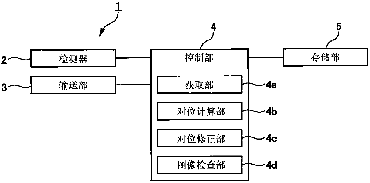
[0035] figure 1 is a functional block diagram of the image inspection device 1 .

[0036] The image inspection apparatus 1 includes: a detector 2 having a linear image sensor that reads an image formed on a sheet; a transport unit 3 that outputs the sheet in conjunction with reading by the detector 2; and a control unit 4 that controls the overall image inspection process. and a storage unit 5 storing data (correction parameters, etc.) necessary for the control unit 4 to perform control.

[0037] The control unit 4 includes an acquisition unit 4a, an alignment calculation unit 4b, an alignment correction unit 4c, and an image inspection unit 4d.

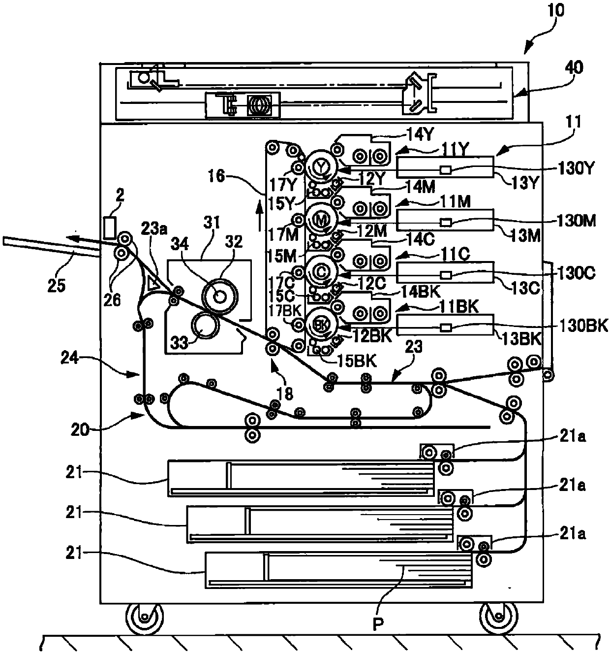
[0038] The acquiring unit 4a acquires the figure 2 ) data of an output target image for image formation on paper. In the following description, an output target image is referred to a...

no. 2 approach example >

[0090] Next, a second embodiment example of the present invention will be described.

[0091] Also in the second embodiment, the image inspection apparatus 1 and the image forming apparatus 10 are applied as they were described in the first embodiment. figure 1 as well as figure 2 structure shown.

[0092] In the second embodiment, as described below, the flow of processing at the time of proof printing and mass printing is different from that of the first embodiment. In the second embodiment example, in Image 6 In the variable region V and the non-variable region NV described above, different contamination detection processes are performed at the time of mass printing.

[0093] below Figure 8 as well as Figure 9 The image inspection process shown in the flowchart of is executed by, for example, the CPU constituting the control unit 4 .

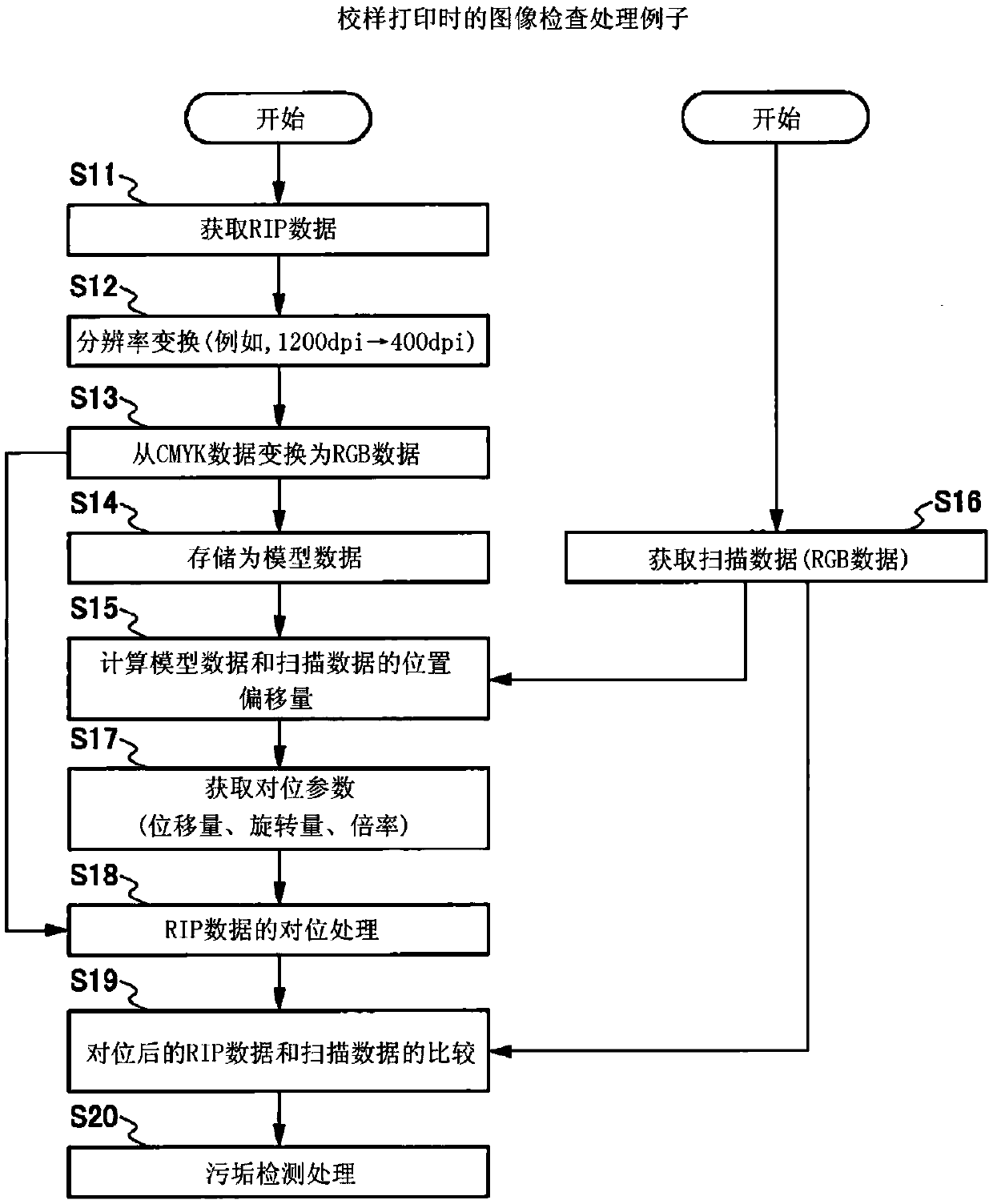
[0094] [2-1. Image inspection processing (during proof printing)]

[0095] Figure 7 It is a flowchart showing the flow of image...


PUM


Abstract

The invention provides an image inspection apparatus and a computer-readable recording medium storing a program. The image inspection apparatus can operate in a short time with an operation processingamount having little position processing, and can conduct inspection in real time. The image inspection apparatus includes an acquirer (4a) that acquires a targeted image to form an image; an alignment calculator (4b) that calculates a correction parameter in order to align a targeted image with a read image; an alignment corrector (4c) that corrects at least one of a targeted image and a read image by using the correction parameter; and an image inspector (4d) that determines a flaw in a read image based on a difference between the targeted image and the read image corrected by the alignmentcorrector (4c). The alignment corrector (4d) saves the correction parameter on a page basis and uses the correction parameter corresponding to a page including an image when aligned.

Description

technical field [0001] The present invention relates to an image inspection device for inspecting an image formed on paper by an image forming apparatus, and a computer-readable recording medium storing a program for executing the image inspection. Background technique [0002] Conventionally, an image inspection device that optically reads an image formed on a paper surface by an image forming device to check whether the image has been correctly formed has been put into practical use. By inspecting an image with an image inspection device, for example, local contamination of the image can be detected. [0003] When an inspection is performed by an image inspection device, it is necessary to correct the misalignment between the original image and the image to be inspected formed on paper or the like, and to accurately align the two images. [0004] The positional shift of the two images occurs when printing on paper and scanning the image on the printed paper. [0005] Dur...

Claims


Application Information

Patent Timeline
Patent Type & Authority Applications(China)
IPC IPC(8): G03G15/00
CPCG03G15/50H04N1/00005H04N1/00328B41F33/0036G01N21/892G06T7/0004G06T2207/30144
Inventor 津江靖久
Owner KONICA MINOLTA INC
Why Eureka
Try Eureka