
An air flow meter sensor fault simulation detection joint and its use method

A technology of sensor faults and air flow meters, which is applied to simulators, simulators for space navigation conditions, instruments, etc., can solve problems such as unsatisfactory fault diagnosis training results, failure to obtain vehicle fault diagnosis and detection environment, etc., and achieve fault simulation And detection is simple and practical, good training effect, good training effect

Active Publication Date: 2021-10-01
上海中侨职业技术大学 +2
View PDF12 Cites 0 Cited by
  • Summary
  • Abstract
  • Description
  • Claims
  • Application Information

AI Technical Summary

Problems solved by technology

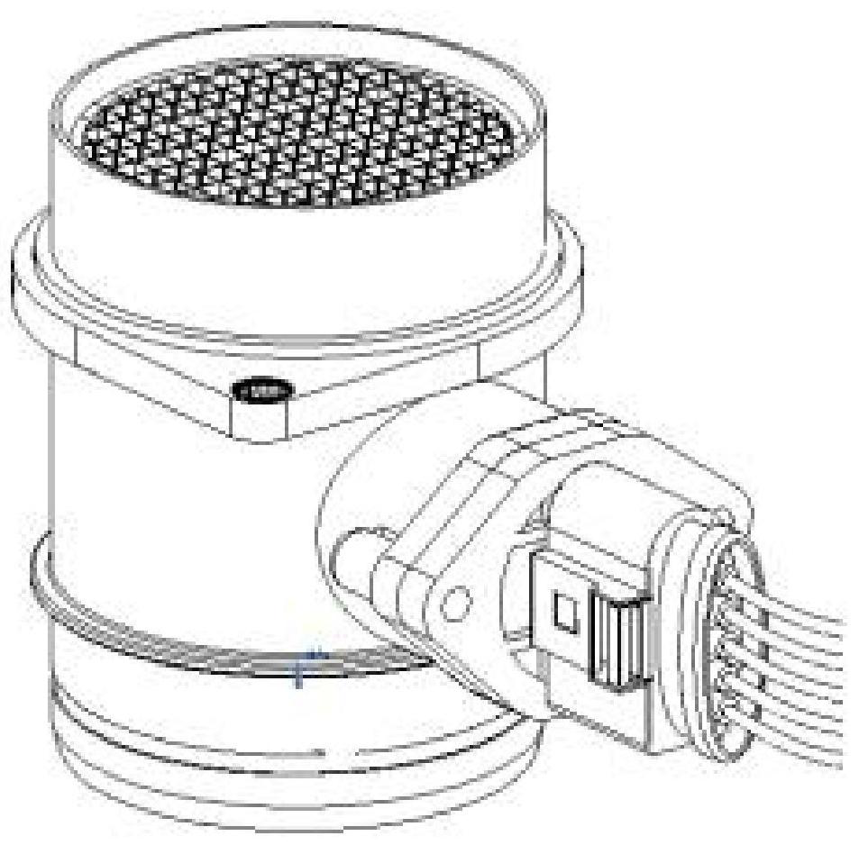
[0002] Automobile fault diagnosis training is a very important course in vocational colleges. In automobile fault diagnosis training, air flow meters are generally used to measure the flow of gas, which is conducive to the detection of flow as an important control parameter (instructions attached figure 1 As shown), the currently commonly used fault diagnosis bench method uses the circuit diagram plus panel detection port method on the bench panel. Since the detection process does not touch the actual vehicle sensor, it is impossible to obtain the real detection environment of the vehicle fault diagnosis. The training effect is not ideal, and the power plug needs to be unplugged during the detection process to cause the circuit to be disconnected
[0003] In the prior art, this kind of charged detection usually needs to be detected after breaking the wire. Therefore, we propose an air flow meter sensor fault simulation detection joint and its use method. The present invention does not need to break the wire for detection. A fault diagnosis detection joint is installed between the connection plugs, which has fault setting and detection functions to solve the above problems

Method used


Image

  • An air flow meter sensor fault simulation detection joint and its use method
  • An air flow meter sensor fault simulation detection joint and its use method
  • An air flow meter sensor fault simulation detection joint and its use method

Examples


Embodiment Construction

[0040] In order to make the object, technical solution and advantages of the present invention clearer, the present invention will be further described in detail below through the accompanying drawings and embodiments. However, it should be understood that the specific embodiments described here are only used to explain the present invention, and are not intended to limit the scope of the present invention.

[0041] It should be noted that when an element is said to be "disposed on, provided with" another element, it may be directly on the other element or there may be an intervening element, and when an element is considered to be "connected" to another element, It may be directly connected to another element or there may be a centering element at the same time. The terms "vertical", "horizontal", "left", "right" and similar expressions are used in this document The only implementation.

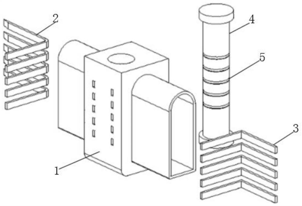
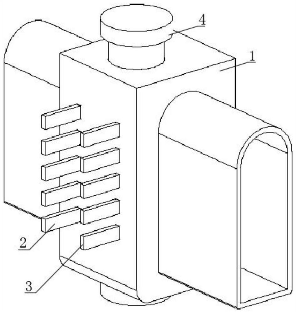
[0042] Please refer to the attached Figure 1-5 , the present invention provides a tec...


PUM


Abstract

The invention discloses an air flowmeter sensor fault simulation detection joint and its use method. There is a horizontally penetrating installation channel between the middle part of the housing and the interface at the left end of the housing, and the top surface of the middle part of the housing is vertically provided with a channel communicating with the installation channel. Hole, the first pin with a bent portion located in the interface at the left end of the housing; the second pin with a bent portion located in the interface at the right end of the housing, which can perform fault simulation and failure on the connecting plug Detection; an on-off switch for controlling the on-off relationship between the first pin and the second pin; by moving the on-off switch up and down to switch the state between the first pin and the second pin, the fault can be quickly performed Simulation and testing, the training has a high degree of fidelity and has a good training effect.

Description

technical field [0001] The invention relates to the related technical field of sensor fault simulation detection, in particular to an air flow meter sensor fault simulation detection joint and a use method thereof. Background technique [0002] Automobile fault diagnosis training is a very important course in vocational colleges. In automobile fault diagnosis training, air flow meters are generally used to measure the flow of gas, which is conducive to the detection of flow as an important control parameter (instructions attached figure 1 As shown), the currently commonly used fault diagnosis bench method uses the circuit diagram plus panel detection port method on the bench panel. Since the detection process does not touch the actual vehicle sensor, it is impossible to obtain the real detection environment of the vehicle fault diagnosis. The training effect is not ideal, and the power plug needs to be unplugged during the detection process to cause the circuit to be disconn...

Claims


Application Information

Patent Timeline
Patent Type & Authority Patents(China)
IPC IPC(8): G09B9/00
CPCG09B9/00
Inventor 龚勉
Owner 上海中侨职业技术大学
Learn More