
Physical experiment teaching demonstration model

A technology of physical experiments and models, applied in the field of teaching models, can solve the problems of single demonstration experiment, lack of coherence in experiments, and lack of sense of participation of students, so as to achieve the effect of improving efficiency, improving teaching efficiency and strong functionality.

Active Publication Date: 2019-04-16
邹忠毅
View PDF11 Cites 8 Cited by
  • Summary
  • Abstract
  • Description
  • Claims
  • Application Information

AI Technical Summary

Problems solved by technology

[0004] However, this scheme has the following problems: the demonstration experiment is relatively simple, and students have no sense of participation, and there is no coherence between experiments

Method used


Image

  • Physical experiment teaching demonstration model
  • Physical experiment teaching demonstration model
  • Physical experiment teaching demonstration model

Examples


Embodiment 1

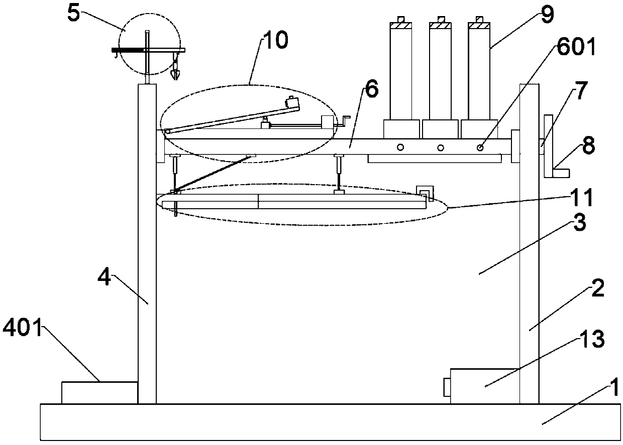
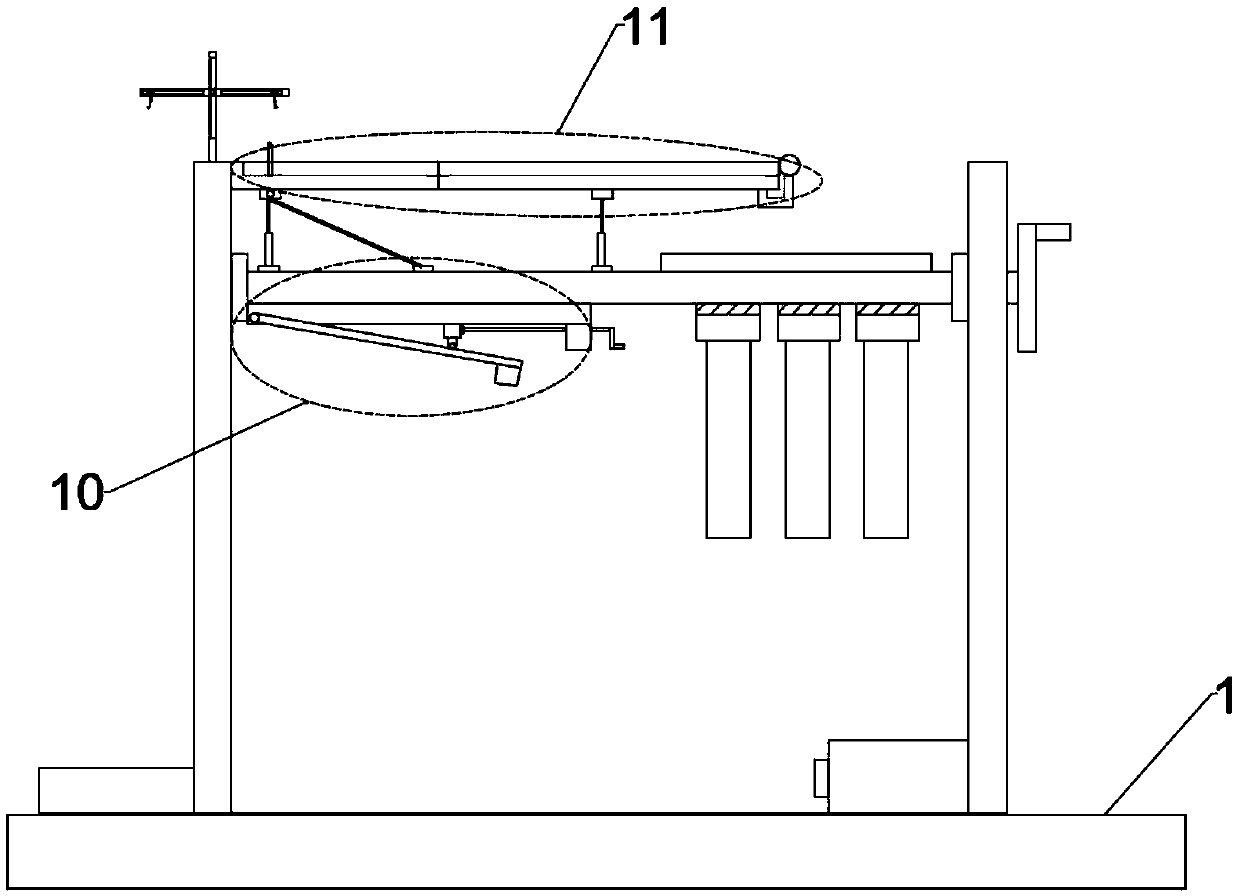
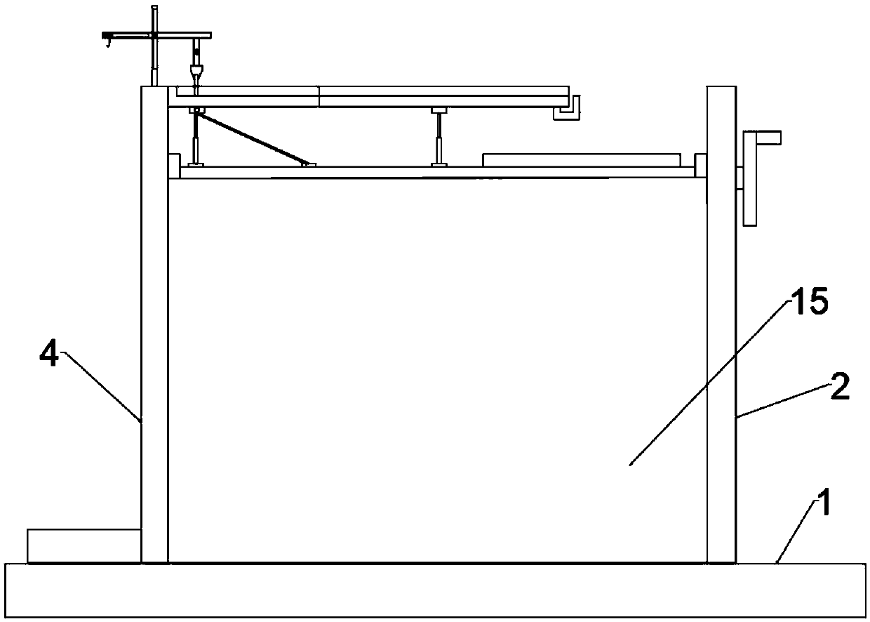
[0043] Such as figure 1 , figure 2 as well as image 3 As shown, the physical experiment teaching demonstration model includes a base 1, and the base 1 is fixed with a first support plate 15, a second support plate 4, a third support plate 3 and a fourth support plate 2 along the vertical direction. A rotating shaft 7 is arranged between the support plate 4 and the fourth support plate 2, and one end of the rotating shaft 7 runs through the wall of the fourth support plate 4 and is connected with a rotary handle 8, and the test bench 6 is fixed on the rotating shaft 7. The upper surface of 6 is provided with a first mechanical demonstration mechanism 10 and a first free-fall demonstration mechanism 9, and the lower surface of the experimental platform 6 is provided with a second mechanical demonstration mechanism 11;

[0044] Such as Figure 4 As shown, the first mechanical demonstration mechanism 10 includes a base plate 101, the lower surface of the base plate 101 is fix...

Embodiment 2

[0050] This embodiment is a further optimization made on the basis of Embodiment 1. Specifically, the electromagnet fixing device 103 includes an electromagnet, a switch 1032 that can control whether the electromagnet is energized, and an electromagnet chuck 1031. Mains connection, when in use, the switch is turned on, the electromagnet is energized, the electromagnetic chuck 1031 will absorb and position the magnetic experiment block, turn the handle during demonstration, and turn off the switch at the same time, the magnetic experiment block slides on the slant plate 102, and the slant plate 102 is lifted up , students can observe the experiment intuitively.

Embodiment 3

[0052] This embodiment is a further optimization made on the basis of embodiment 2, as Figure 10 , 11 As shown, specifically the clamping device includes a clamping seat 9042, the central position of the clamping seat 9042 is fixed with a micro-cylinder 9041, and the piston rod of the micro-cylinder 9041 is provided with a central pin 9043, and both sides of the central pin 9043 are The movable connection has jaw 9044.


PUM


Abstract

The invention discloses a physical experiment teaching demonstration model. The physical experiment teaching demonstration model comprises a base, a first supporting plate, a second supporting plate,a third supporting plate and a fourth supporting plate are fixedly arranged on the base in the vertical direction, a rotary shaft is arranged between the second supporting plate and the fourth supporting plate, and one end of the rotary shaft penetrates through the wall part of the fourth supporting plate to be connected with a rotary handle. The rotary shaft is fixedly provided with an experimenttable, a first mechanics demonstration mechanism and a first free-fall demonstration mechanism are arranged on the upper surface of the experiment table, and a second mechanics demonstration mechanism is arranged on the lower surface of the experiment table. A third mechanics demonstration mechanism is arranged on the second supporting plate. By means of the physical experiment teaching demonstration model, students can be made to have senses of participation, and experiments can be consistently demonstrated, the functions are powerful, and the practicability is high.

Description

technical field [0001] The invention relates to the field of teaching models, in particular to a demonstration model for teaching physics experiments. Background technique [0002] Experiment is a major branch of physics. In physics teaching, physics experiments run through elementary school, junior high school and even high school. In physics experiment teaching, teachers especially explain support force, friction force, pressure and force decomposition and state of motion. In the process, it is difficult for students to understand only by oral explanations. Only through live demonstrations by teachers and students' personal experiments can students have a deep memory and a thorough understanding. This requires a mechanical demonstration device for students that can be practically operated and demonstrated. [0003] Through retrieval, the application publication number is CN 106504620 A Chinese patent "a physical projectile experiment demonstration device", which includes a...

Claims


Application Information

Patent Timeline
IPC IPC(8): G09B23/08G09B23/10
CPCG09B23/08G09B23/10
Inventor 邹忠毅
Owner 邹忠毅
Features
  • Generate Ideas
  • Intellectual Property
  • Life Sciences
  • Materials
  • Tech Scout
  • Unparalleled Data Quality
  • Higher Quality Content
  • 60% Fewer Hallucinations
Learn More