A short circuit proof connector

A connector and short-circuit proof technology, which is applied in the direction of connection, components and circuits of the connection device, can solve the problems of fire, water conduction, short-circuit of the lower connector, etc., and achieves the effect of low cost and simple structure

Active Publication Date: 2021-06-04
JOYOUNG CO LTD
View PDF11 Cites 0 Cited by
  • Summary
  • Abstract
  • Description
  • Claims
  • Application Information

AI Technical Summary

Problems solved by technology

When the kettle body is separated from the power base, the lower connector is still connected with high voltage, and the two connecting ends are exposed at this time. If the lower connector is sprayed with water, the two electrical connecting ends may be wet and conduct, resulting in a short circuit of the lower connector. , causing a fire

Method used


Image

  • A short circuit proof connector
  • A short circuit proof connector
  • A short circuit proof connector

Examples


Embodiment 1

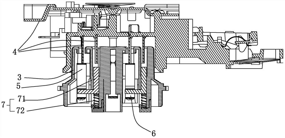
[0036] see figure 1 , figure 2 , a short-circuit-proof, short-circuit-proof connector, comprising a first component 3 and a second component 4 electrically coupled to each other.

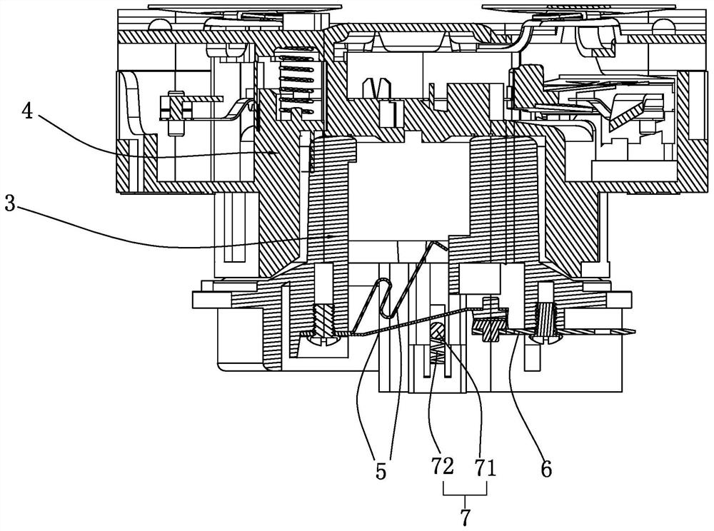
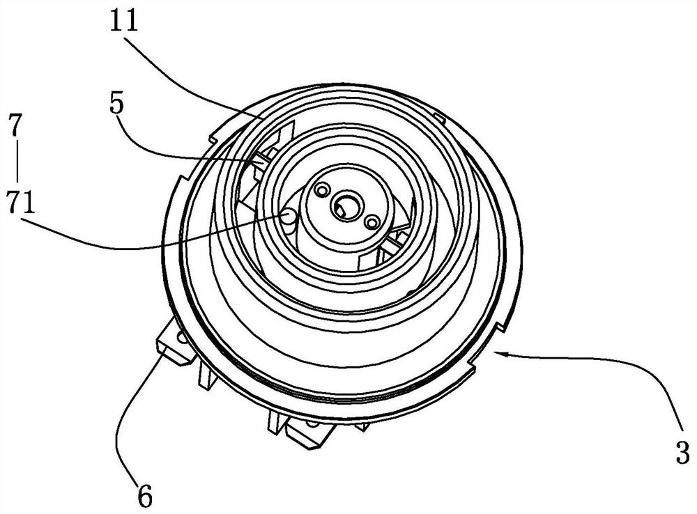
[0037] see figure 2 , image 3 and Figure 4 , the first part 3 includes a housing 11, and the housing 11 is provided with at least one set of integral wiring elements 6 and connecting elements 5, and the connecting elements 5 are used to cooperate with the second part 4 when the first part 3 is matched with the second part 4. Component 4 is electrically connected,. When the first part 3 is mated with the second part 4 , the connecting element 5 is in electrical contact with the wiring element 6 .

[0038] Specifically, two sets of connection elements 6 and connection elements 5 are provided on the housing 11. The two connection elements 6 are connected to the live wire and the neutral wire respectively, and the two connection elements 6 are used to make electrical contact with different conn...

Embodiment 2

[0061] The technical difference between this embodiment and Embodiment 1 is that, see figure 2 , when the first part 3 is matched with the second part 4, the connecting element 5 and the wiring element 6 have three kinds of electrical contacts, the three kinds of electrical contacts of the connecting element 5 and the wiring element 6 in this embodiment can be connected The two separation modes of the element 5 and the wiring element 6 can be combined arbitrarily.

[0062] In the first electrical contact mode between the connection element 5 and the connection element 6, the connection element 6 and the connection element 5 rely on the second part 4 to overcome the driving force of the driver 7, and the connection element 5 and the connection element 6 can easily realize electrical contact. touch.

[0063] see figure 2 and image 3 and Figure 4 , the connecting element 5 is separated from the wiring element 6 by the driving force of the driving part 7. When the first pa...

Embodiment 3

[0075] A household appliance is a water boiler, a health pot or a soybean milk machine.

[0076] see Figure 13 , the above-mentioned household appliance includes a body 1 and a machine base 2, and the body 1 is a heating container for containing and heating liquid. The top of the machine base 2 is provided with a first part 3 , and the bottom of the body 1 is provided with a second part 4 , when the machine body 1 is placed on the machine base 2 , the second part 4 is coupled with the first part 3 under the action of gravity. At this time, the cooperation of the first part 3 and the second part 4 can completely rely on the gravity of the body 1 itself, so that the body 1 and the base 2 do not separate, and there is no need for artificial force to make the two cooperate, which is more labor-saving.

[0077] This embodiment includes the structures of embodiment one and embodiment two, see figure 2 , when the first part 3 and the second part 4 are separated, the connecting el...


PUM


Abstract

The invention discloses an anti-short circuit connector, which comprises a first part and a second part which cooperate with each other. Components, the wiring elements are in communication with the neutral wire or live wire, the connecting elements are used for electrical connection with the second part, when the first part is matched with the second part, the connecting element is in electrical contact with the wiring element; the first part and the When the second component is separated, the connection element is separated from the wiring element, and the distance between them is greater than 1.5mm. Since the connection element and the wiring element are separated, the distance between the two is greater than 1.5mm, so when the first part is sprayed with water, it can effectively reduce the possibility of the connection element and the wiring element being connected by water and electricity, so as to prevent the connection element and the wiring element from being shocked by high voltage Through and conduction, the connecting element can be stably disconnected from the high-voltage power supply.

Description

technical field [0001] The invention relates to the field of household electrical appliances, in particular to a short-circuit-proof connector. Background technique [0002] At present, the Chinese patent with the notification number CN10609957A discloses an electrical connector assembly, which includes an upper connector and a lower connector matched with the upper connector. The upper connector is located at the bottom of the kettle body, and the lower connector is located on the power base. Generally, the lower connector has two connection terminals for electrical connection with the upper connector, and the two connection terminals are respectively connected to the neutral wire and the live wire. After the kettle body is lifted from the power base, the upper connector is separated from the lower connector. When the kettle body is separated from the power base, the lower connector is still connected with high-voltage electricity. At this time, the two connecting ends are...

Claims


Application Information

Patent Timeline
Patent Type & Authority Patents(China)
IPC IPC(8): H01R33/96H01R33/945H01R13/66
CPCH01R13/66H01R13/6683H01R33/945H01R33/96
Inventor 朱泽春曹郑汤立华范勃刘斌
Owner JOYOUNG CO LTD
Why Eureka
Try Eureka