Antenna type inductive electricity-taking device

A technology of inductive power collection and induction voltage, which is applied in the direction of circuit devices, electrical components, etc., to achieve the effects of stable power supply, clean and environmentally friendly devices, and convenient power collection

Inactive Publication Date: 2019-04-16
WUHAN UNIV OF TECH
View PDF7 Cites 1 Cited by
  • Summary
  • Abstract
  • Description
  • Claims
  • Application Information

AI Technical Summary

Problems solved by technology

It can be seen that the power supply problem of this type of device has become the bottleneck of its development.

Method used


Image

  • Antenna type inductive electricity-taking device
  • Antenna type inductive electricity-taking device
  • Antenna type inductive electricity-taking device

Examples


Embodiment Construction

[0018] In order to make the object, technical solution and advantages of the present invention clearer, the present invention will be further described in detail below in conjunction with the accompanying drawings and embodiments.

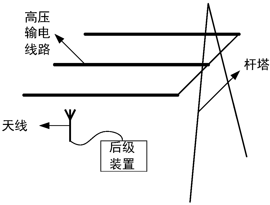
[0019] like figure 1 As shown, the present invention provides an antenna-type induction power-taking device, including an antenna and a spark plug arranged around a high-voltage transmission line, such as figure 2 and Figure 5 As shown, the antenna collects the magnetic field energy around the high-voltage transmission line to obtain the induced voltage, and the spark plug processes the induced voltage collected by the antenna to obtain the pulse current. The pulse current is converted into low-voltage direct current through the voltage conversion circuit and the energy management system in turn to supply power for the load circuit.

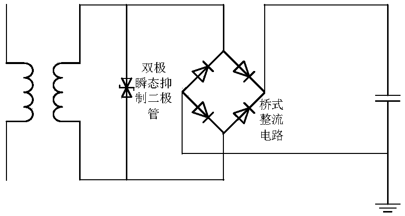
[0020] like image 3 As shown, the voltage conversion circuit is composed of a transformer, a bipolar transient...


PUM


Abstract

The invention discloses an antenna type inductive electricity-taking device, which comprises an antenna and a spark plug which are arranged around a high-voltage transmission line. The antenna collects the energy of a magnetic field around the high-voltage power transmission line to obtain an inductive voltage. The spark plug processes the inductive voltage collected by the antenna to obtain a pulse current. The pulse current is converted into a low-voltage direct current through a voltage conversion circuit, an energy management system and a load circuit in sequence. The low-voltage direct current is supplied to monitoring equipment to power on the monitoring equipment. According to the invention, the magnetic field around the high-voltage power transmission line is utilized, and the electricity is taken based on the voltage induced by the antenna. Therefore, the charging problem of the power transmission line monitoring equipment is solved.

Description

technical field [0001] The invention relates to the field of power supply for monitoring equipment, and more specifically relates to an antenna-type inductive power-taking device. Background technique [0002] In recent years, the development of power monitoring is a major trend. The degree of intelligence of the power system is getting higher and higher, and there are more and more parameters that need to be monitored. Therefore, more and more sensors and corresponding monitoring equipment are installed in the power system. While monitoring the state of the power system, these monitoring devices face power supply problems. For example, the device for monitoring high-voltage transmission line insulators is very troublesome to charge after the battery power is used up. It is necessary for staff to remove the monitoring device installed at a high place on the transmission line and take it to a charging station with low-voltage mains power. Charge at the power source. It ca...

Claims


Application Information

Patent Timeline
Patent Type & Authority Applications(China)
IPC IPC(8): H02J50/12H02J5/00
CPCH02J5/005H02J50/12
Inventor 吴细秀汪博川李超群张圆圆文博杨振武杨芷宁庞文龙侯慧
Owner WUHAN UNIV OF TECH
Why Eureka
Try Eureka