Automatic charging device for recessed electric rails of electric vehicle driven on highway

An automatic charging device and electric vehicle technology, applied in electric vehicles, circuit devices, battery circuit devices, etc., can solve the problems that electric vehicles cannot store a large amount of electric energy, the power receiving device is large, and the two-way waterproof rail charging road is not suitable, etc.

Active Publication Date: 2013-10-23
山东省未来人才科技有限公司
View PDF4 Cites 13 Cited by
  • Summary
  • Abstract
  • Description
  • Claims
  • Application Information

AI Technical Summary

Problems solved by technology

[0002] At present, the application of existing electric vehicle charging technology mainly relies on the support of a wide range of fixed charging stations. However, charging stations cannot store a large amount of electric energy for electric vehicles in a short period of time. The result is a waste of time and inconvenience. The main obstacle to the development of electric vehicles
There is a technical solution that can wirelessly power electric vehicles while driving on the road. Although it has not yet reached maturity and practicality, the future development direction
The patent document with the publication number CN102629400A discloses an invention patent for ...

Method used


Image

  • Automatic charging device for recessed electric rails of electric vehicle driven on highway
  • Automatic charging device for recessed electric rails of electric vehicle driven on highway
  • Automatic charging device for recessed electric rails of electric vehicle driven on highway

Examples


Embodiment Construction

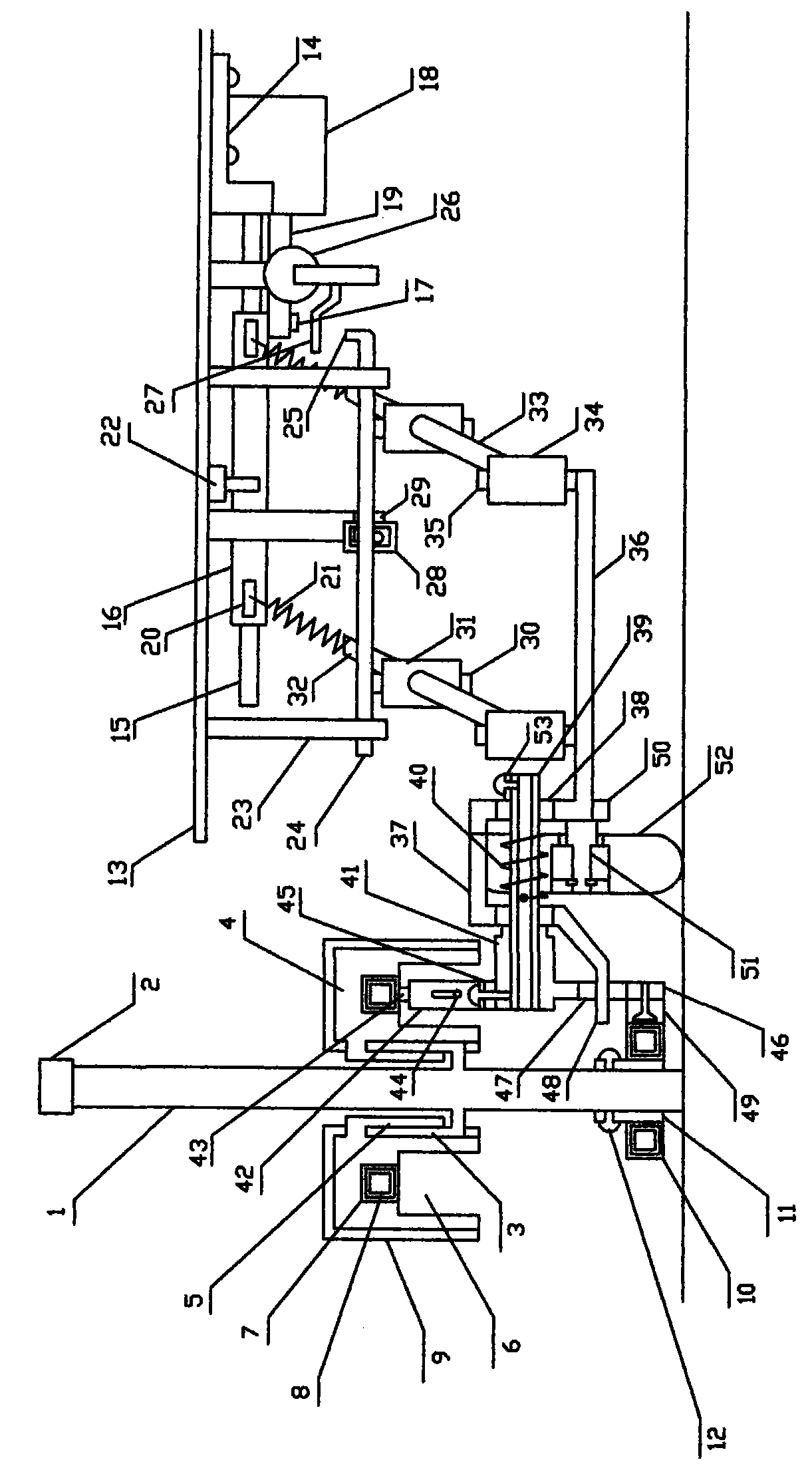
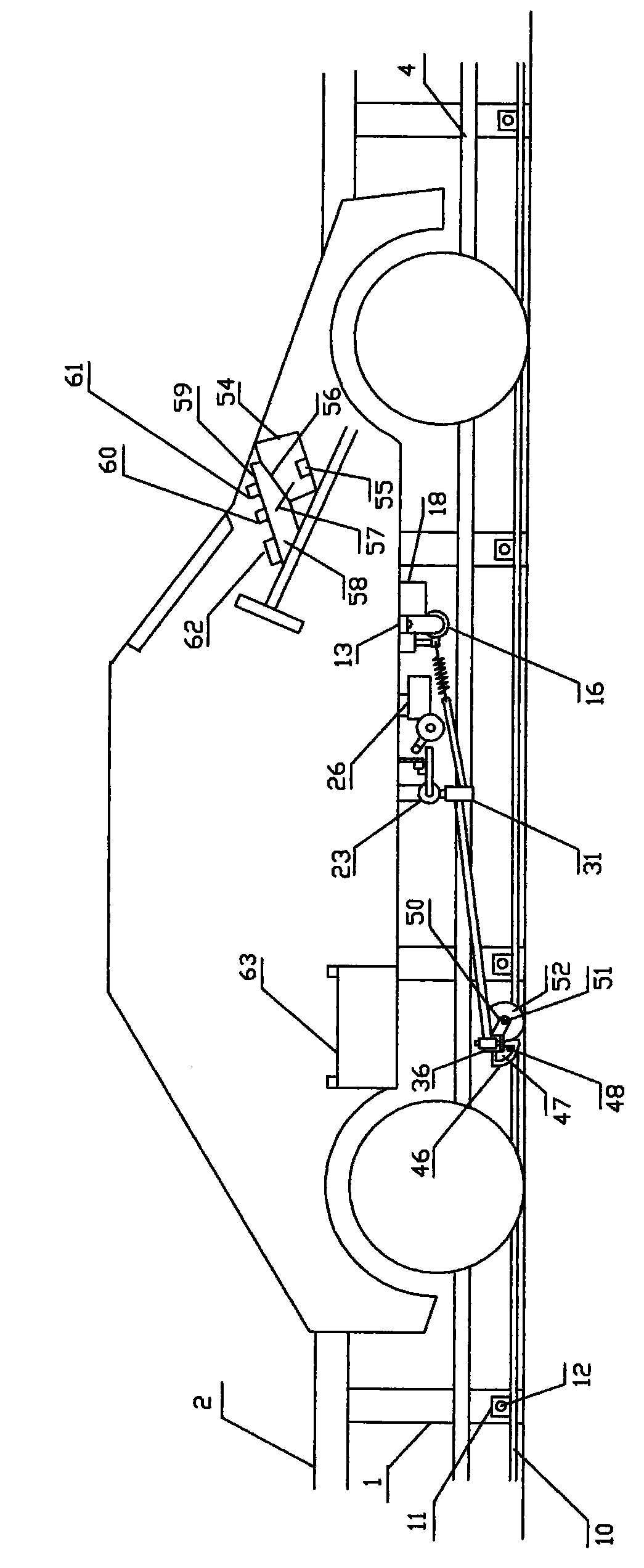
[0021] exist figure 1 , figure 2 In the schematic diagram of the rear view structure and the right side view structure of the electric vehicle road driving invisible electric rail automatic charging device shown, the two-way invisible electric rail charging road is a set of several two-way roads with isolation bars in the middle. On the road section of the driveway, there are two one-way lanes on the left and right sides of the separation fence. The separation fence is provided with some main vertical bars 1. The main vertical bars are stainless steel square tubes. The upper end of the main vertical bars is a long horizontal bar 2. L-shaped stainless steel support 3, left and right n-type plastic tracks 4 are installed on the left and right L-shaped stainless steel supports, left and right L-shaped plastic supports 5 are shaped on the top of the left and right n-shaped plastic tracks, articulated symmetrically with the left and right L-shaped stainless steel supports, and the...


PUM


Abstract

The invention discloses an automatic charging device for recessed electric rails of electric vehicles driven on a highway. A left recessed electric rail and a right recessed electric rail are arranged on the two sides of the middle part of vertical rods of partition fences in the middle of a bi-directional lane; a left grounded electric rail and a right grounded electric rail are arranged on the two sides of the lower ends of the vertical rods, and are not arranged at the crossroads, so that a pavement is not occupied, transportation and city appearance are not affected, and electric vehicles can be charged automatically as long as moving near to the double electric rails of the partition fences; a power supply cavity opening below a n-shaped plastic track of each recessed electric rail faces downwards, and a power supply copper square pipe is hidden at the upper part inside the cavity to prevent the invasion of water sprayed from various directions; the head ends of the left electric rail and the right electric rail pass through an underground cable, and are connected with a power supply of a toll power feeding station; an arc ground wire carbon brush of an automatic transformation carbon brush rack of a vehicle-mounted electrical control automatic current collector rotates backwards automatically through the elastic force and sliding friction force between the arc ground wire carbon brush and an grounded electric rail copper square pipe; a live wire carbon brush rack erects upwards, a positioning claw positions the live wire carbon brush rack in the vertical state, the upper end of a live wire carbon brush is positioned in the middle of the copper square pipe inside a recessed electric rail cavity and receives electricity through sliding and connection; when the vehicle leaves from the double electric rails, the current collector is shrunk automatically, and the vehicle bottom can be concealed.

Description

Technical field: [0001] The invention relates to a technical device for the electrification of urban traffic, in particular to an automatic charging device for invisible electric rails of an electric vehicle running on roads. Background technique: [0002] At present, the application of existing electric vehicle charging technology mainly relies on the support of a wide range of fixed charging stations. However, charging stations cannot store a large amount of electric energy for electric vehicles in a short period of time. The result is a waste of time and inconvenience. The main obstacle to the development of electric vehicles. There is a technical solution that can wirelessly power electric vehicles while driving on the road. Although it has not yet reached maturity and practicality, it is the future development direction. The patent document with the publication number CN102629400A discloses an invention patent for an automatic charging device for waterproof guide rails...

Claims


Application Information

Patent Timeline
IPC IPC(8): G07F15/06H02J7/00
Inventor 朱幕松
Owner 山东省未来人才科技有限公司
Why Eureka
Try Eureka