Land marker and application method thereof

A scriber and field technology, applied in the field of scriber devices, can solve the problems of inconspicuous scriber lines, inconvenient operation, easy to bend, etc., and achieve the effects of simple structure, better effect, and reduced waste.

Active Publication Date: 2019-04-19
济宁市农业科学研究院
View PDF8 Cites 4 Cited by
  • Summary
  • Abstract
  • Description
  • Claims
  • Application Information

AI Technical Summary

Problems solved by technology

[0006] The above-mentioned device uses the staff to pull the pull rod to drive the marking knife to mark the line, but the labor intensity is high, and it is inconvenient to operate in the field, and the line drawn by the marking knife is not obvious enough, and it is easy to bend, which is not as clear as lime powder.

Method used


Image

  • Land marker and application method thereof
  • Land marker and application method thereof
  • Land marker and application method thereof

Examples


Embodiment 1

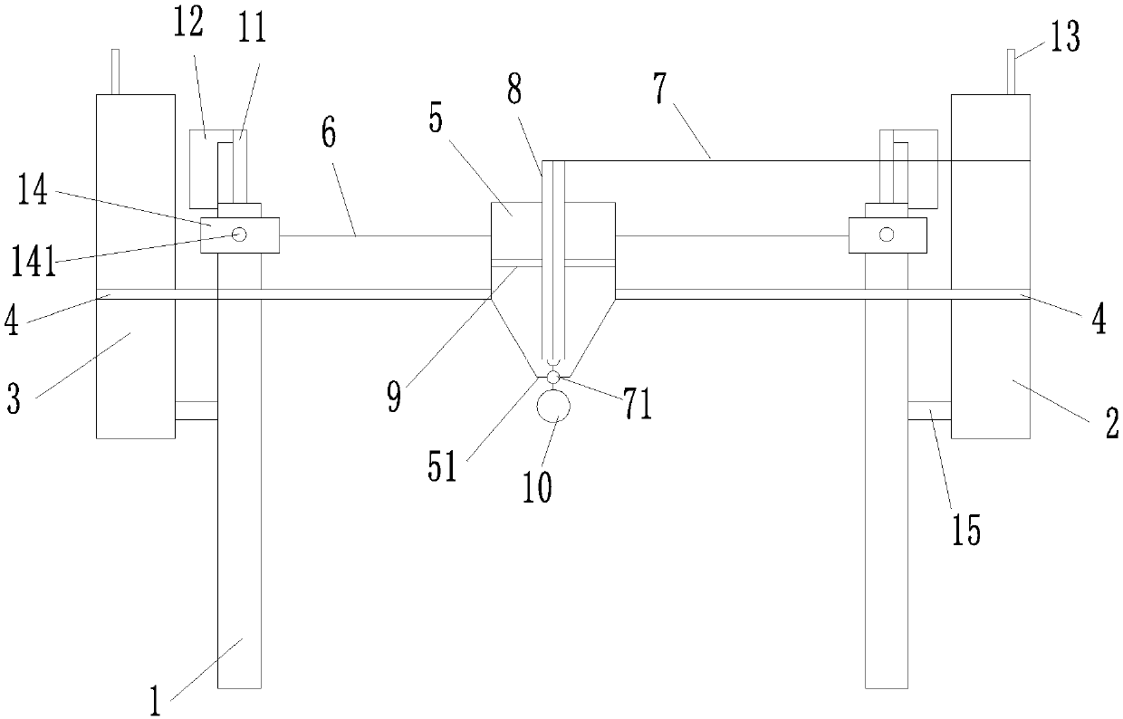
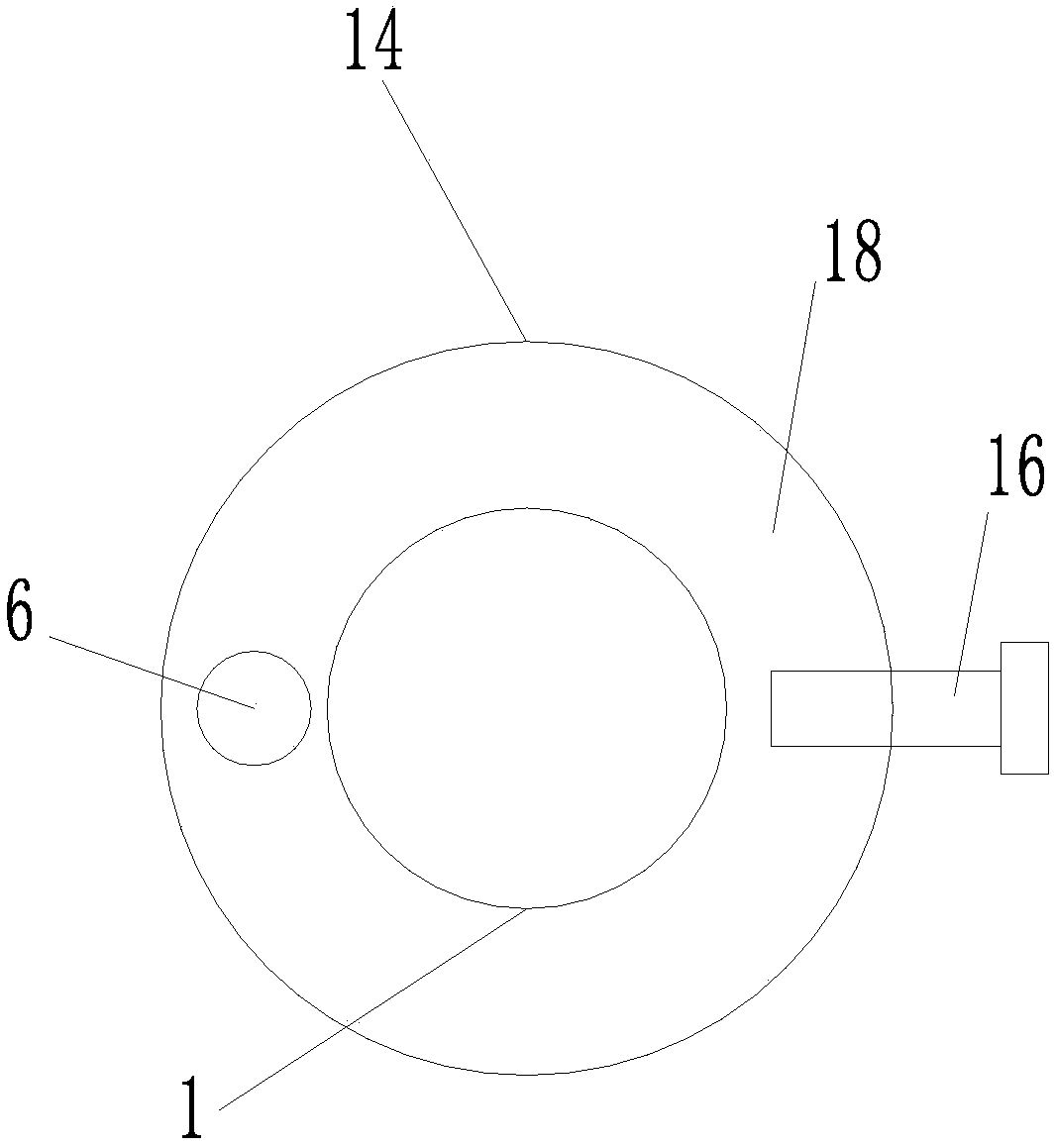
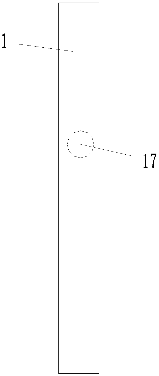
[0043] like Figure 1-4 As shown, a field marker proposed in this embodiment includes a hopper 5. Further, in order to feed more smoothly, the lower end of the hopper 5 can be tapered, and a powder outlet is also provided at the bottom of the hopper 5. 51. The outer wall of the hopper 5 is connected with a coiled sheet steel bar 4. Further, there are two coiled sheet steel bars 4, and the other ends of the coiled sheet steel bar 4 are fixedly connected with first The drum 2 and the second drum 3 are advantageous. The first drum 2 and the second drum 3 can be cylindrical, and the first drum 2 and the second drum 3 are respectively connected to the two support rods 1 through brackets 15. The first roller 2 and the second roller 3 can directly realize the reciprocating movement of the hopper 5 on the one hand, without the need for the staff to turn back at both ends of the field, and on the other hand, the staff does not need to forcefully pull the marker to mark the line, only n...

Embodiment 2

[0055] like Figure 5-8 As shown, other structures are the same as the first embodiment, and the difference from the first embodiment is that a fixed plate 20 is provided at the upper end of the hopper 5, and the number of the fixed plates 20 is provided with two and arranged symmetrically, and the first fixed plate 20 is installed Pulley 19 can make hopper 5 slide on steel wire rope 6 more conveniently, convenient blanking. In order to reduce the production cost, lighten the weight of the whole device, and facilitate the operation of the staff, the shapes of the first drum 2 and the second drum 3 can be set as I-shaped. In order to make the pulling of the stay cord 6 more convenient, a second pulley 22 is arranged in the hollow tube 8, which can prolong the service life of the stay cord 6 and reduce friction. In addition, a second through hole 23 is also provided on the support rod 1, and the pull cord 6 is connected to the first roller 2 through the second through hole 23. ...


PUM


Abstract

The invention discloses a land marker, comprising a bucket. The lower end of the bucket is provided with a powder outlet; the outer wall of the bucket is connected with two traction members; the otherends of the traction members are fixedly connected with a first drum and a second drum; the first drum and the second drum are connected to two support rods respectively; each support rod is providedwith a first through hole; the traction members are passed through the first through holes and wound to the first drum and the second drum respectively; the bucket is also slidably connected with a fastener; the two ends of the fastener are connected with the support rods respectively. The land marker is simple in structure; the bucket can be reciprocated directly through the first drum and the second drum, so that round trips of workers between the two ends of a land are not required; a ball lifting mechanism allows the powder outlet to be opened and closed; a spherical arc face allows limestone powder to slide down along the arc face, forming uniform continuous lines; a protrusion helps effectively prevent the powder outlet from being blocked by the limestone powder; the land marker isconvenient to operate and simple and practical.

Description

technical field [0001] The invention relates to the technical field of marking devices, in particular to a field marking device and a method for using the same. Background technique [0002] In agricultural science experiments, in order to ensure the accuracy of the experimental data and make the sowing row and plant spacing as consistent as possible, it is necessary to mark the sowing position in the experimental field before sowing. At present, the method of marking is at first to mark the row marks in the longitudinal direction according to the needs of the sowing row spacing. Since the distance in the longitudinal direction is longer, a mechanically driven row marker can be used to operate. When rowing horizontally, the following methods are mainly used: First, the method of pulling the horizontal line is adopted. Two operators stretch the thin rope, and one person in the middle steps on it or presses it with a wheelbarrow along the thin rope. Bending, resulting in erro...

Claims


Application Information

Patent Timeline
Patent Type & Authority Applications(China)
IPC IPC(8): A01C14/00
CPCA01C14/00
Inventor 蒋飞杨小华吴静曾苏明宋春林吴秋平韩成卫
Owner 济宁市农业科学研究院
Why Eureka
Try Eureka