
Driving device for taking off and entering last machine for shoe body

A driving device, a technology for removing the last, which is applied to shoe lasts, insoles, shoe uppers, etc., can solve the problems of affecting the stability of the structural cloud, inappropriate movements, and high energy consumption, and achieves convenient counting, energy saving, and high degree of automation. Effect

Active Publication Date: 2022-02-15
JIHUA LAB
View PDF6 Cites 0 Cited by
  • Summary
  • Abstract
  • Description
  • Claims
  • Application Information

AI Technical Summary

Problems solved by technology

[0003] At present, the production of shoe lasts is made by mechanical processing, and the strength is stable and can be reused. However, at present, a specific shoe last is specified for a shoe size and shoe shape. The higher the accuracy and shape requirements of the last, the higher the processing accuracy and difficulty, the higher the cost, but the trend of people's aesthetics changes rapidly, and the replacement of shoe lasts is also very fast, which has resulted in the replacement of a large number of shoe lasts, cost Increase
[0004] The process of making shoes involves lasting and taking off the last. The lasting completes the processing of the shoe body, and after the shoe body is finished, it involves taking off the last. The machines currently on the market generally only involve the lasting or only the lasting. There are few structures that integrate the lasting and lasting into one, and at present, on the market, no matter whether it is a lasting machine or a lasting machine, all drives are completed by air cylinders, which need to be equipped with air pumps to ensure stable air flow. The setting of the air source and air pump needs a lot of energy, and if the air source is unstable, it is easy to cause improper movement and affect the stability of the entire structure.

Method used


Image

  • Driving device for taking off and entering last machine for shoe body
  • Driving device for taking off and entering last machine for shoe body
  • Driving device for taking off and entering last machine for shoe body

Examples


Embodiment Construction

[0027] It should be noted that, in the case of no conflict, the embodiments of the present invention and the features in the embodiments can be combined with each other.

[0028] In describing the present invention, it should be understood that the terms "center", "longitudinal", "transverse", "upper", "lower", "front", "rear", "left", "right", " The orientations or positional relationships indicated by "vertical", "horizontal", "top", "bottom", "inner" and "outer" are based on the orientations or positional relationships shown in the drawings, and are only for the convenience of describing the present invention and Simplified descriptions, rather than indicating or implying that the device or element referred to must have a particular orientation, be constructed and operate in a particular orientation, and thus should not be construed as limiting the invention. In addition, the terms "first", "second", etc. are used for descriptive purposes only, and should not be understood ...


PUM


Abstract

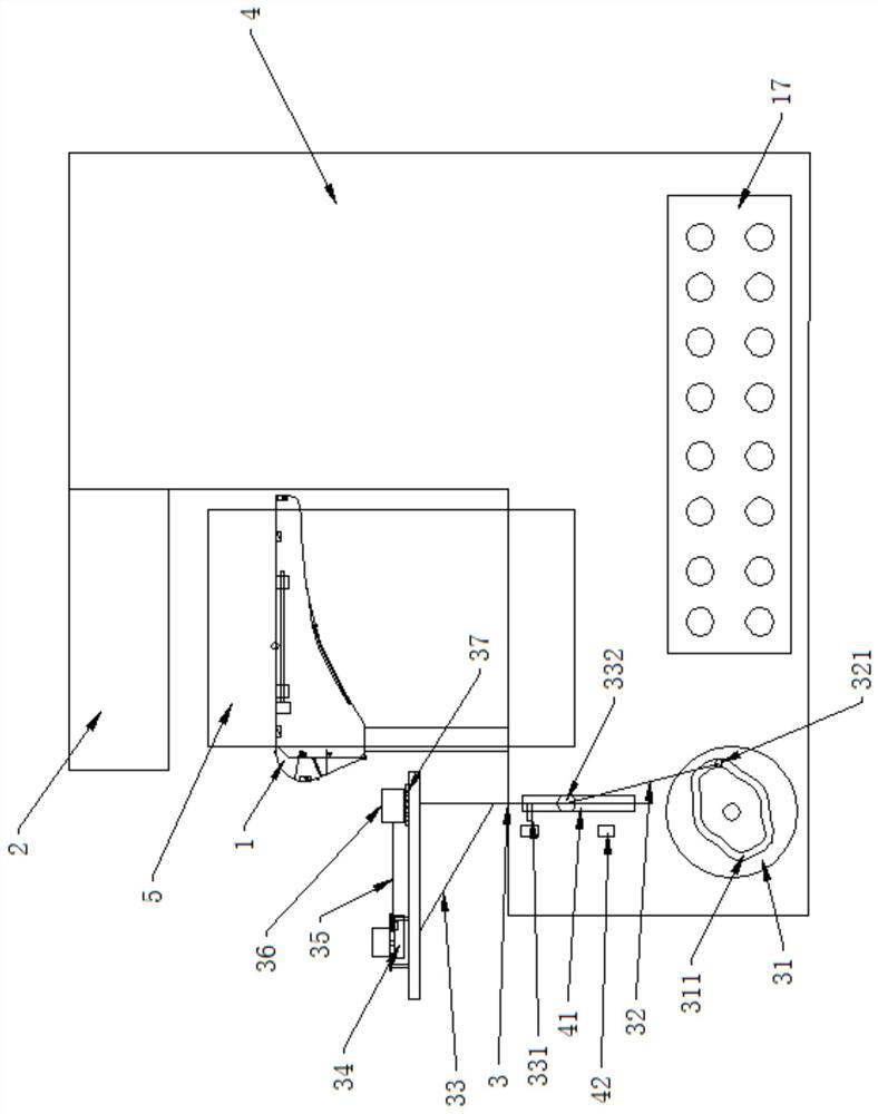
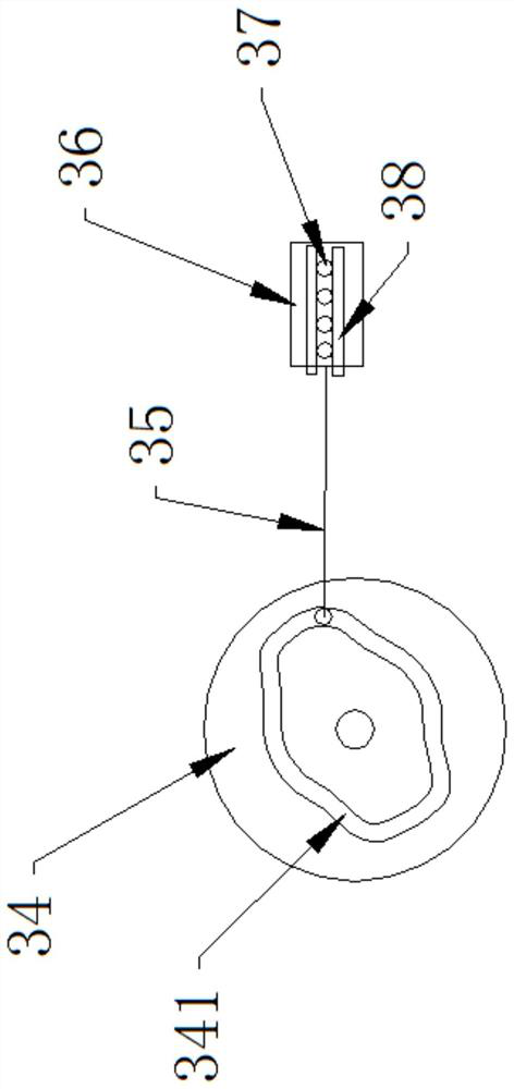
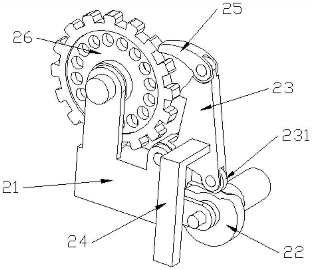
The invention provides a driving device for a machine for taking off the last and inserting the last into the last as a shoe body, which belongs to the field of shoemaking equipment and includes a fixed frame on which an inverted shoe last is fixed, and a flattening assembly is arranged above the shoe last. The left and right sides are equipped with clamping components, and the rear end of the shoe tree is provided with a stripping component. The stripping component includes a rising cam, a rising driving rod and a lifting frame. The rising cam is rotatably connected to the fixed frame. Drive groove, the first drive groove drives the lifting frame to move up and down through the rising drive rod. The upper end of the lifting frame is provided with a translation cam, a translation driving rod and a last block. The translation cam is arranged horizontally and is connected to the lifting frame in rotation. The second drive slot drives the last block to move left and right through the translation drive rod. The power drive of the present invention makes the operation of the whole structure more stable and reliable, greatly reduces the failure rate, and reduces energy consumption, saves energy and is more environmentally friendly.

Description

technical field [0001] The invention belongs to the field of shoe-making equipment, and relates to a driving device for a machine for taking off the last and inserting the last into the last for the role of a shoe body. Background technique [0002] Shoe last, a traditional Chinese shoemaking utensil, also known as last, is popular in most parts of the country. The wooden product is cut into the shape of the foot and filled in the shoe to fit the foot. The shoe last is the matrix of the shoe and the molding mold of the shoe. The shoe last not only determines the shape and style of the shoe, but also determines whether the shoe fits and protects the foot. Therefore, the design of the shoe last must be based on the shape of the foot, but it cannot be the same as the shape of the foot, because the shape, size, stress, etc. of the foot change when the foot is at rest or in motion. , the performance of raw and auxiliary materials, and the wearing environment and conditions are ...

Claims


Application Information

Patent Timeline
Patent Type & Authority Patents(China)
IPC IPC(8): A43D11/00A43D15/00A43D9/00A43D3/10
CPCA43D3/10A43D9/00A43D11/00A43D15/00
Inventor 孙云权齐立哲赵延治黄世军
Owner JIHUA LAB
Learn More