Cutter used for manufacturing drum rack plate

A cutting machine and drum stand technology, which is applied in the direction of manufacturing tools, sawing components, sawing equipment, etc., can solve the problems that the board cannot be kept flat, the rate of cutting defective products is high, and the cutting efficiency is low, so as to achieve consistent size and work efficiency. High, avoid the effect of local warping

Pending Publication Date: 2018-11-16
临清市森源博乐器配件制造有限公司
View PDF12 Cites 2 Cited by
  • Summary
  • Abstract
  • Description
  • Claims
  • Application Information

AI Technical Summary

Problems solved by technology

In the prior art, the technical problem of cutting wood boards is that the boards in the cutting state cannot be kept flat, resulting in a high rate of cutting defective products, and many processes are done manually by hand, resulting in low cutting efficiency

Method used


Image

  • Cutter used for manufacturing drum rack plate
  • Cutter used for manufacturing drum rack plate
  • Cutter used for manufacturing drum rack plate

Examples


Embodiment Construction

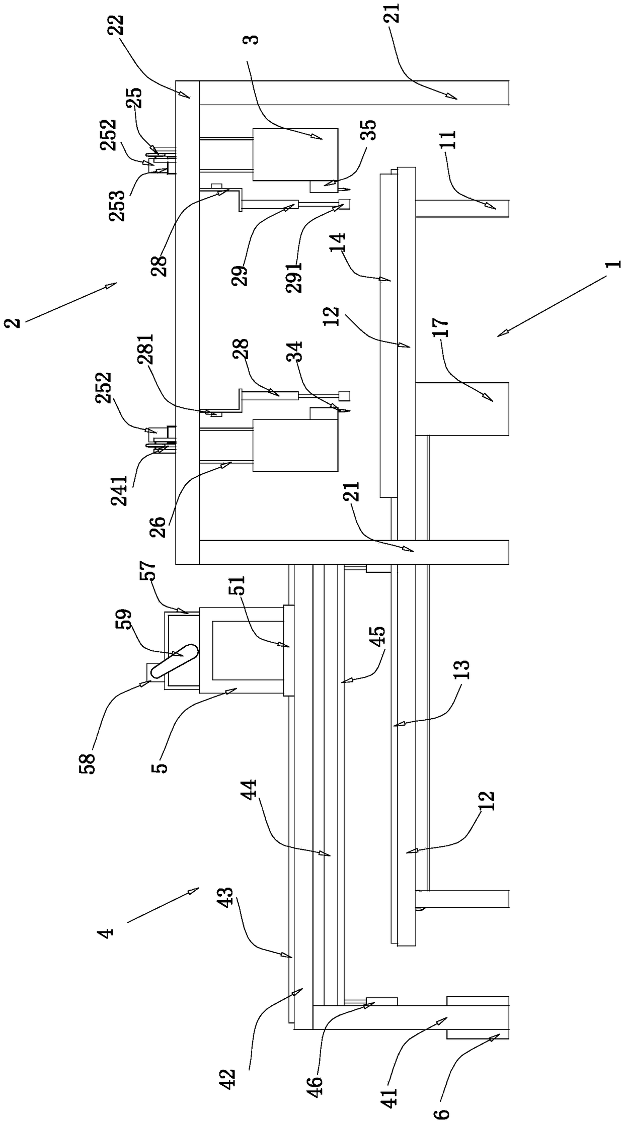
[0036] Such as Figure 1 to Figure 11 As shown, the present invention mainly includes a conveying mechanism 1, an edge trimming mechanism 2, a first flattening mechanism, a second flattening mechanism and a cutting mechanism 4. The present invention will be described in detail below with reference to the accompanying drawings.

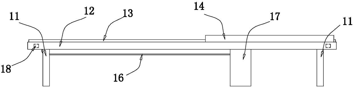
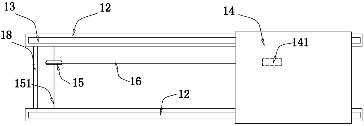
[0037] Such as Figure 1 to Figure 3 As shown, the conveying mechanism 1 mainly includes a first leg 11, a first beam 12, a first guide rail 13, a conveying platform 14 and a driving unit. There are four first legs 11, and the four first legs are respectively located in a rectangular shape. On the four vertices of the front side, a first beam 12 is arranged between the tops of the two first legs on the front side, and the first legs are connected together by the first beam. The front and rear crossbeams are fixedly connected together by the first connecting rod 18, and the first leg, the first crossbeam and the first connecting rod constitute the firs...


PUM


Abstract

The invention discloses a cutter used for manufacturing a drum rack plate, and the cutter is used for manufacturing drum rack plates of various drums. The cutter comprises a conveying mechanism, a trimming mechanism, a first planishing mechanism, a second planishing mechanism and a cutting mechanism; the conveying mechanism comprises a first rack, a conveying table arranged on the first rack and adriving unit which drives the conveying table to move leftwards and rightwards; the first planishing mechanism comprises a first pressing rod and a compaction air cylinder which drives the first pressing rod; the trimming mechanism comprises a second rack, a first sliding block arranged on the second rack, a first feeding unit which drives the first sliding block and a cutting unit which is fixedly connected with the first sliding block; the cutting mechanism comprises a third rack, a walking rack arranged on the third rack, a second feeding unit which drives the walking rack to move back andforth, a cutting unit which is fixedly connected with the second sliding block and a third feeding unit which drives the walking rack to move leftwards and rightwards; and the second planishing mechanism comprises a square frame which is located in a plane and a lifting air cylinder which drives the square frame. By adopting the cutter, wood plates can be cut conveniently.

Description

technical field [0001] The invention relates to the technical field of drum frame manufacture, in particular to a cutting machine for manufacturing drum frame plates. Background technique [0002] The drum kit is an important part of rock instruments. The drums in the drum kit generally include bass drums, snare drums, and tom drums. The drum frame boards of these drums are generally made of wooden materials. Drum stand boards are generally formed by bonding multiple boards, and these boards are obtained by cutting a larger board. In the prior art, the technical problem of cutting wood boards is that the boards in the cutting state cannot be kept flat, resulting in a high rate of cutting defective products, and many processes are done manually by hand, resulting in low cutting efficiency. Contents of the invention [0003] The object of the present invention is to provide a cutting machine for manufacturing drum frame plates for facilitating the processing of drum frame p...

Claims


Application Information

Patent Timeline
Patent Type & Authority Applications(China)
IPC IPC(8): B27B5/06B27B5/29B27B5/04B27B25/04B27G3/00B27B31/00B27M3/00
CPCB27B5/04B27B5/06B27B5/29B27B25/04B27B31/00B27G3/00B27M3/00
Inventor 倪荣岐高云红高继航倪景煜
Owner 临清市森源博乐器配件制造有限公司
Why Eureka
Try Eureka