Surface wiper of machining center machine tool
A processing center and wiper technology, applied to dryers, chemical instruments and methods, lighting and heating equipment, etc., can solve the problems of low wiping efficiency and easy reflection on people, so as to improve wiping efficiency and speed up drying speed effect
- Summary
- Abstract
- Description
- Claims
- Application Information
AI Technical Summary
Problems solved by technology
Method used
Image

Examples
Embodiment 1
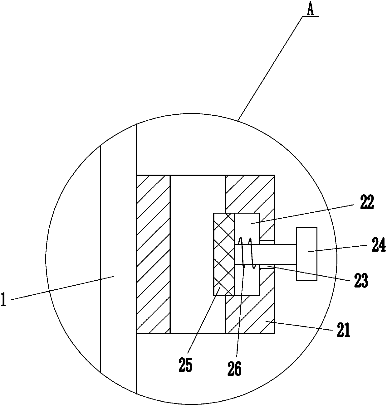
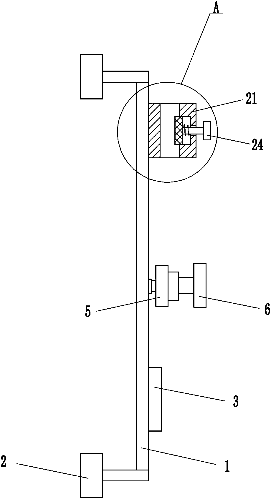
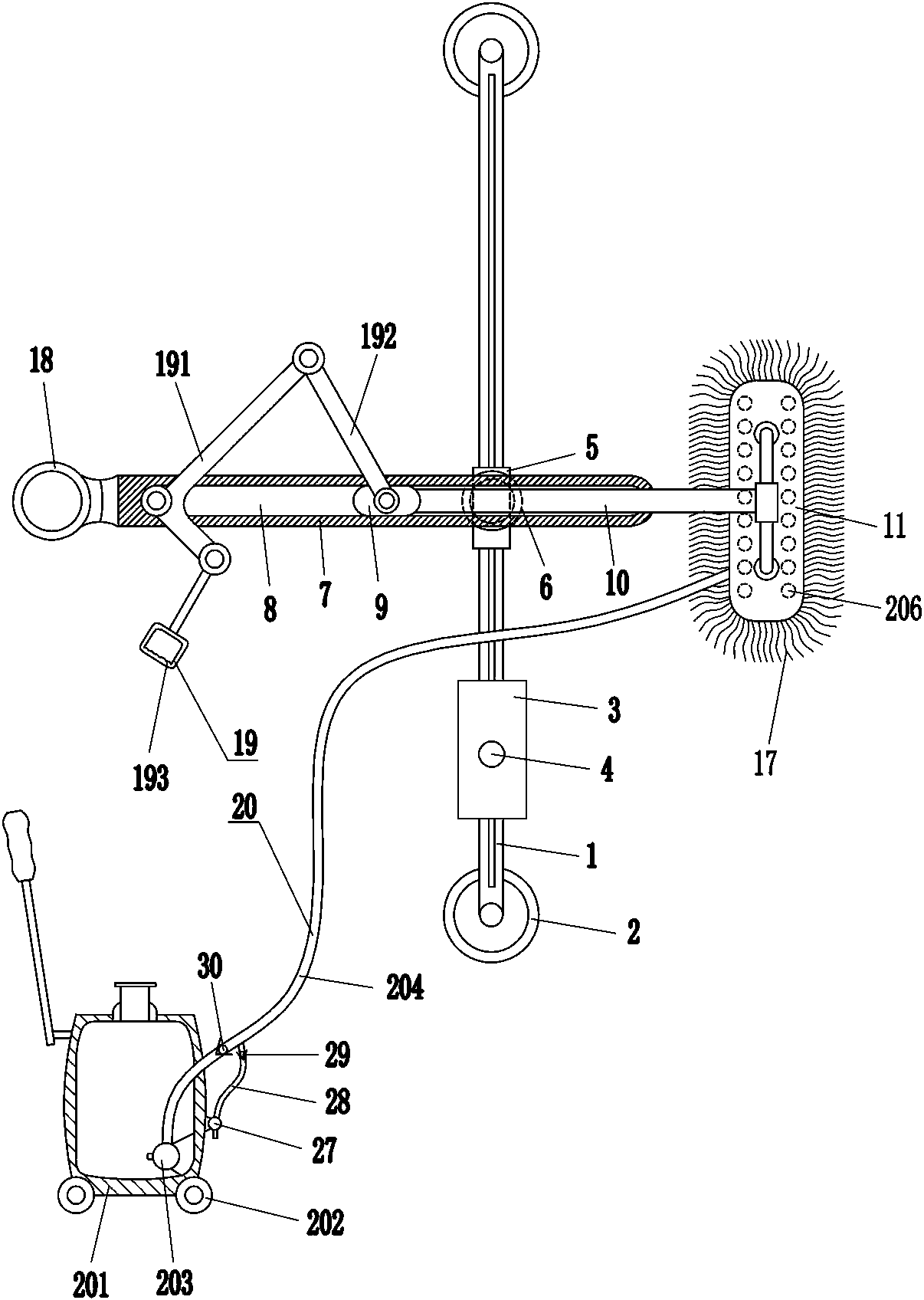
[0017] A machining center machine tool surface wiper, such as Figure 1-3 As shown, it includes a slide rail 1, an electromagnet 2, a power supply 3, a switch 4, a slider 5, a rotating shaft 6, a movable plate 7, a slider 9, a moving rod 10, a mounting block 11, a screw 13, a mesh plate 14, and a nut 16. Hairbrush 17, handle 18 and driving mechanism 19, the upper and lower ends of slide rail 1 are bolted with electromagnet 2, the lower part of the front side of slide rail 1 is bolted with power supply 3, and the front side of power supply 3 is installed with electromagnet 2 for controlling The switch 4, the switch 4 is connected with the power supply 3, the two electromagnets 2 are connected with the switch 4, the slide rail 1 is provided with a sliding block 5 which plays a guiding role, and the slide block 5 is located above the power supply 3, The front side of the slider 5 is rotatably connected with a T-shaped rotating shaft 6, and the movable plate 7 is fixedly connected...
Embodiment 2
[0019] A machining center machine tool surface wiper, such as Figure 1-3 As shown, it includes a slide rail 1, an electromagnet 2, a power supply 3, a switch 4, a slider 5, a rotating shaft 6, a movable plate 7, a slider 9, a moving rod 10, a mounting block 11, a screw 13, a mesh plate 14, and a nut 16. Hairbrush 17, handle 18 and driving mechanism 19, the upper and lower ends of slide rail 1 are bolted with electromagnet 2, the lower part of the front side of slide rail 1 is bolted with power supply 3, and the front side of power supply 3 is installed with electromagnet 2 for controlling The switch 4, the switch 4 is connected with the power supply 3, the two electromagnets 2 are connected with the switch 4, the slide rail 1 is provided with a sliding block 5 which plays a guiding role, and the slide block 5 is located above the power supply 3, The front side of the slider 5 is rotatably connected with a T-shaped rotating shaft 6, the movable plate 7 is fixedly connected to ...
Embodiment 3
[0022] A machining center machine tool surface wiper, such as Figure 1-3 As shown, it includes a slide rail 1, an electromagnet 2, a power supply 3, a switch 4, a slider 5, a rotating shaft 6, a movable plate 7, a slider 9, a moving rod 10, a mounting block 11, a screw 13, a mesh plate 14, and a nut 16. Hairbrush 17, handle 18 and driving mechanism 19, the upper and lower ends of slide rail 1 are bolted with electromagnet 2, the lower part of the front side of slide rail 1 is bolted with power supply 3, and the front side of power supply 3 is installed with electromagnet 2 for controlling The switch 4, the switch 4 is connected with the power supply 3, the two electromagnets 2 are connected with the switch 4, the slide rail 1 is provided with a sliding block 5 which plays a guiding role, and the slide block 5 is located above the power supply 3, The front side of the slider 5 is rotatably connected with a T-shaped rotating shaft 6, the movable plate 7 is fixedly connected to ...
PUM
 Abstract
Description
Claims
Application Information
PatSnap Eureka turns technology decisions into work you can execute. Powered by our Innovation Knowledge Graph, it runs expert workflows across engineering, life sciences, materials and intellectual property. Get your review-ready output in minutes.


