[0026] In order to make the objectives, technical solutions, and advantages of the embodiments of the present invention clearer, the technical solutions in the embodiments of the present invention are described clearly and completely. Obviously, the described embodiments are part of the embodiments of the present invention, not all of them. example. Based on the embodiments of the present invention, all other embodiments obtained by those of ordinary skill in the art without creative work shall fall within the protection scope of the present invention.
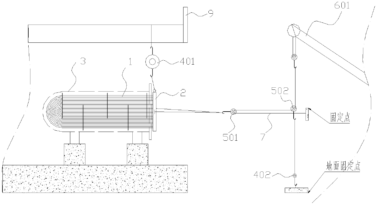
[0027] The embodiment of the application is a method for removing the tube bundle of a horizontal U-tube heat exchanger, such as Figure 1~2 As shown, the horizontal U-tube heat exchanger well known to those skilled in the art includes a cylinder body 3, a tube bundle 1 and a tube sheet 2. For the heavier horizontal U-tube heat exchanger, the horizontal U-tube heat exchanger The most important thing to remove the heat exchanger is to extract the tube bundle 1. The tube bundle 1 is assembled inside the cylinder 3. The existing hoisting equipment can be used with a hoist for extraction. However, when the site environment is more complicated, the equipment surroundings are limited, and there are only In an environment that is operable in one direction and does not have the assistance of fixed lifting equipment, and the heavier heat exchanger tube bundles, when the traditional lifting equipment is used with a hoist for extraction under such conditions, the lifting equipment is difficult to tow Maintain balance, which can cause equipment damage.
[0028] Specifically, there is a steel platform above the site, and there are columns on the left and right, which completely cover the periphery of the heat exchanger. For example, the horizontal U-tube heat exchanger, in the actual application process, in order to facilitate the maintenance and monitoring of the horizontal U-tube heat exchanger, a steel frame type second-floor platform 7 will be installed on its upper part, and even some second floors The platform 7 will extend to about 2m in front of the equipment tube plate, and it is the 2m extension that makes it difficult for the lifting equipment to extend in. For this kind of working conditions, when the traditional lifting equipment is used with a hoist to pull out, It is difficult to maintain balance when the lifting equipment is towed, resulting in equipment damage.
[0029] In order to solve the above problems, the specific steps of the embodiment of the present invention are as follows:
[0030] In order to facilitate the connection, five lifting lugs 201 are welded in sequence on the outer circle of the tube plate 2, and they are respectively fixed at twelve, two, three, nine and ten o'clock directions. The structure of the lifting lug 201 can bear vertical and horizontal loads through calculations.
[0031] The first chain hoist 401 is fixed directly above the heat exchanger, and the other end of the first chain hoist 401 is connected to the tube plate 2 of the heat exchanger; specifically, to ensure stability, the heat exchanger is fixed directly above Two first chain hoists 401, one of the connection points of the first chain hoist 401 and the tube plate 2 of the heat exchanger is located at the two o'clock direction of the tube plate;
[0032] The connection point of the other first chain hoist 401 and the tube plate 2 of the heat exchanger is located in the ten o'clock direction of the tube plate, and the hook of the above first chain hoist 401 is matched with the lifting lug 201.
[0033] The tube sheet 1 of the heat exchanger is directly connected to the movable pulley 501. Specifically, the movable pulley 501 is connected to the three o'clock and nine o'clock directions of the tube sheet 1 of the heat exchanger by a rope, which can be connected to the tube sheet 1 The lifting lugs 201 in the three o'clock and nine o'clock directions are equipped with sliding wheels, and then the sliding wheels are connected to the movable pulley 501 by ropes;
[0034] The traction rope 7 bypasses the movable pulley 501, and one end of the traction rope 7 is fixed. Specifically, the fixed point is set on site to ensure traction, such as figure 1 At the middle fixed point, the other end of the traction rope 7 passes through the fixed pulley 502 and is connected to the first crane 601;
[0035] The fixed pulley 502 is connected to one end of the second chain hoist 402, and the other end of the second chain hoist 402 is fixed to the ground;
[0036] The first crane 601 is started to pull the traction rope 7 and the tube bundle 2 is drawn out.
[0037] During the implementation of the above embodiment, the fixed pulley 502 is used to convert the horizontal displacement into the vertical displacement. The movable pulley 501 can reduce the traction caused by friction. In the environment without the assistance of fixed lifting tools, Quickly replace the tube bundle of the heat exchanger. Save manpower, time, and cost.
[0038] During specific implementation, the height of the fixed pulley 502 is consistent with the center elevation of the tube bundle 1. Specifically, the second chain hoist 402 shown is located directly below the fixed pulley 502.
[0039] In the specific implementation process, when the first crane 601 pulls out the tube bundle 1 by pulling the traction rope 7, adjust the connection point of the first chain hoist 401 and the tube bundle 1 to control the concentricity of the tube bundle 1 and the cylinder 3 .
[0040] In the specific implementation process, when the tube bundle 1 is separated from the cylinder 3, the tube bundle 1 is fixed by the second crane 602 to keep the tube bundle 1 level. Specifically, the second crane 602 can be placed on the left front of the heat exchanger or Right front; after the tube bundle 1 is drawn out, the tube bundle 1 is transported away by a forklift 7.
[0041] It should be noted that in this article, relational terms such as first and second are only used to distinguish one entity or operation from another entity or operation, and do not necessarily require or imply one of these entities or operations. There is any such actual relationship or order between. Moreover, the terms "include", "include" or any other variants thereof are intended to cover non-exclusive inclusion, so that a process, method, article or device including a series of elements not only includes those elements, but also includes those that are not explicitly listed Other elements of, or also include elements inherent to this process, method, article or equipment. If there are no more restrictions, the element defined by the sentence "including a..." does not exclude the existence of other same elements in the process, method, article, or equipment that includes the element.
[0042] The above embodiments are only used to illustrate the technical solutions of the present invention, not to limit them; although the present invention has been described in detail with reference to the foregoing embodiments, a person of ordinary skill in the art should understand that: The recorded technical solutions are modified, or some of the technical features are equivalently replaced; these modifications or replacements do not cause the essence of the corresponding technical solutions to deviate from the spirit and scope of the technical solutions of the embodiments of the present invention.