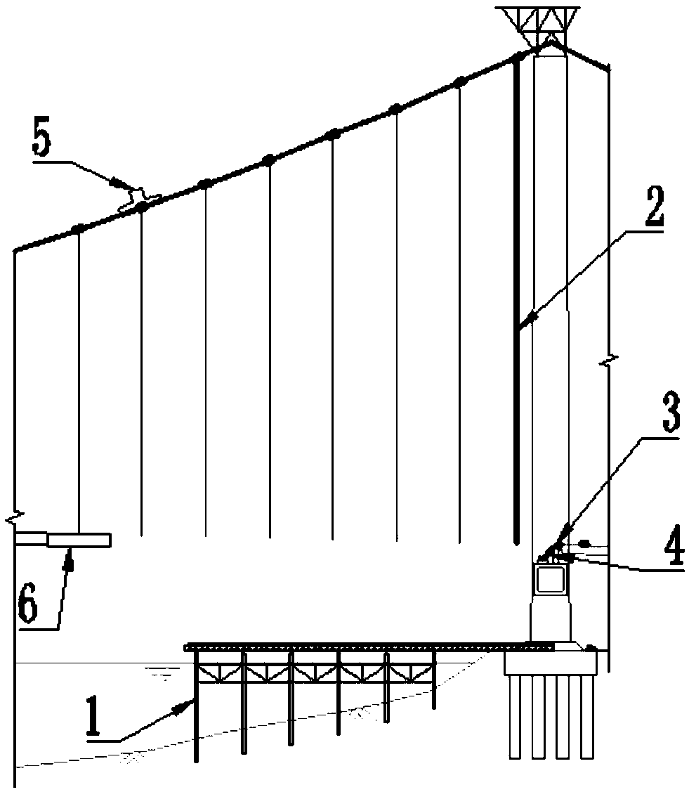
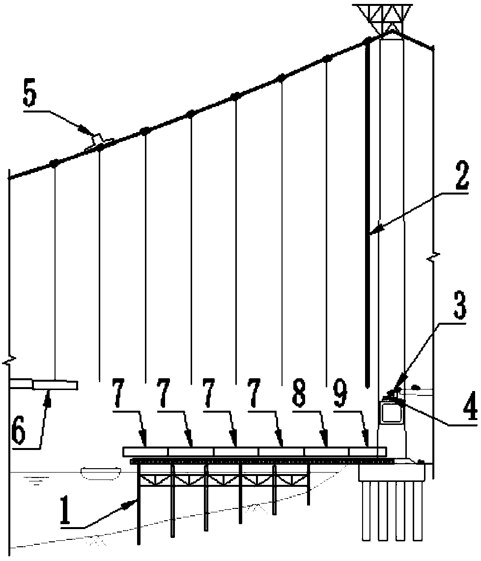
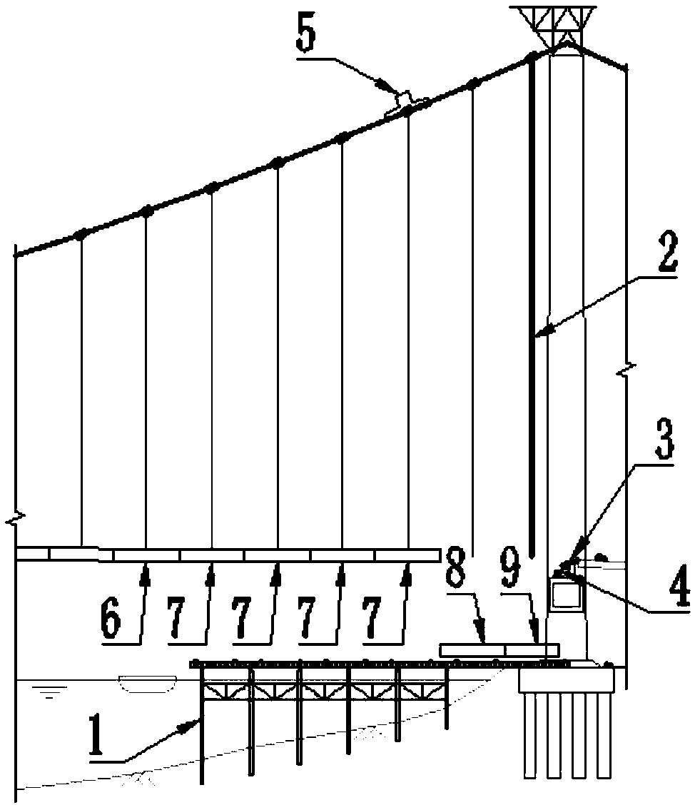
Suspension bridge main span suspension-cable-free beam section mounting method

An installation method and technology of suspension bridges, which are applied in the direction of suspension bridges, bridges, bridge forms, etc., can solve problems such as the influence of hoisting of cable-loaded crane components, and achieve the effects of reducing construction safety risks, saving costs, and facilitating layout

Inactive Publication Date: 2019-04-19
CHINA RAILWAY CONSTR BRIDGE ENG BUREAU GRP +1
View PDF4 Cites 7 Cited by
  • Summary
  • Abstract
  • Description
  • Claims
  • Application Information

AI Technical Summary

Problems solved by technology

[0004] This method needs to set up a beam storage bracket for the non-sling beam section next to the main tower, and the support is mostly a high support; At the main cable, it is necessary to walk back to the beam section in the shoal area to hoist other beams after completing the swing of the beam section without slings, that is, the cable-loaded crane needs to run back and forth on the main cable; the cable-loaded crane usually uses the tower top door The components of the cable-loaded crane are directly hoisted from the site on the side of the middle span of the main tower by using the spreader on the mast on the top of the tower. There is no beam storage bracket for the beam section next to the tower, which will have a certain impact on the hoisting of the cable-loaded crane components.

Method used


Image

  • Suspension bridge main span suspension-cable-free beam section mounting method
  • Suspension bridge main span suspension-cable-free beam section mounting method
  • Suspension bridge main span suspension-cable-free beam section mounting method

Examples


Embodiment Construction

[0031] It should be noted that, in the case of no conflict, the embodiments of the present invention and the features in the embodiments can be combined with each other.

[0032] In describing the present invention, it is to be understood that the terms "center", "longitudinal", "transverse", "upper", "lower", "front", "rear", "left", "right", " The orientations or positional relationships indicated by "vertical", "horizontal", "top", "bottom", "inner" and "outer" are based on the orientations or positional relationships shown in the drawings, and are only for the convenience of describing the present invention and Simplified descriptions, rather than indicating or implying that the device or element referred to must have a particular orientation, be constructed and operate in a particular orientation, and thus should not be construed as limiting the invention. In addition, the terms "first", "second", etc. are used for descriptive purposes only, and should not be understood a...


PUM


Abstract

The invention provides a suspension bridge main span suspension-cable-free beam section mounting method. The method includes steps: (1) installing a beam storage slide supporting frame, a cable loading crane, a temporary suspension cable and a temporary stay cable, and guaranteeing that the cable loading crane is positioned at a hoisting position at the front end of the beam storage slide supporting frame; (2) sequentially transferring land and shoal beam sections, a closure section and a suspension-cable-free beam section to the beam storage slide supporting frame; (3) sequentially hoisting the last normal beam section and land and shoal beam section by the cable loading crane; (4) moving the closure section and the suspension-cable-free beam section towards the front end of the beam storage slide supporting frame by a certain distance; (5) transferring the suspension-cable-free beam section to a main tower crossbeam; (6) closing. The suspension bridge main span suspension-cable-freebeam section mounting method has advantages that beam storage supporting frames close to piers are avoided, so that cost saving is realized, and construction safety risks are reduced.

Description

technical field [0001] The invention belongs to the field of installation of the non-sling beam section of a suspension bridge, in particular to a method for installing the non-sling beam section of the main span of a suspension bridge. Background technique [0002] Suspension bridges are widely used in long-span bridges because of their strong spanning capacity, reasonable force, and low cost. [0003] The main girder of a suspension bridge is generally divided into a general beam section, a land and shallow area beam section, a closing section, and a non-suspension beam section according to the location and construction method. The main girder of suspension bridges is usually constructed using the cable-loaded crane method. After the general beam section is hoisted, the beam section without slings is transported by barge to the front end of the storage girder sliding support of the beam section on land and in the shoal area. The beam slides on the support, and then slides...

Claims


Application Information

Patent Timeline
Patent Type & Authority Applications(China)
IPC IPC(8): E01D21/00E01D11/02
CPCE01D11/02E01D21/00
Inventor 宋伟俊刘长辉陈宁贤龚国锋李向海曲江峰张庆霍艳雷张静章耀林朱林达朱永盛冯文园于龙波张培炎李明泽
Owner CHINA RAILWAY CONSTR BRIDGE ENG BUREAU GRP
Why Eureka
Try Eureka