Device and method for monitoring and controlling residual carbon combustion during hot sintering mineral cooling process

A technology of cooling process and thermal sintering, which is applied in the field of devices for monitoring and controlling residual carbon combustion in the cooling process of hot sintered ore, and in the field of devices for monitoring residual carbon combustion of thermal sintered ore, which can solve problems such as secondary combustion of residual carbon

Active Publication Date: 2019-04-19
ZHONGYE-CHANGTIAN INT ENG CO LTD
View PDF10 Cites 1 Cited by
  • Summary
  • Abstract
  • Description
  • Claims
  • Application Information

AI Technical Summary

Problems solved by technology

However, when there is air leakage in the system (especially the feed and discharge of the vertical cooling device), the oxygen content of the circulating gas increases rapidly, and the oxygen content detect

Method used


Image

  • Device and method for monitoring and controlling residual carbon combustion during hot sintering mineral cooling process
  • Device and method for monitoring and controlling residual carbon combustion during hot sintering mineral cooling process
  • Device and method for monitoring and controlling residual carbon combustion during hot sintering mineral cooling process

Examples


Embodiment approach

[0130] According to the second embodiment of the present invention, a method for monitoring and controlling the combustion of residual carbon in the cooling process of hot sintered ore is provided:

[0131] A method for monitoring and controlling the combustion of residual carbon in the cooling process of hot sinter ore or a method for monitoring and controlling the combustion of residual carbon in the cooling process of hot sinter using the above-mentioned device for monitoring and controlling the combustion of residual carbon in the cooling process of hot sinter, the method comprising the following steps :

[0132] 1) The device starts to run, and the first temperature measuring device 5, the first flow detection device 6, the second temperature measuring device 7 and the second flow detection device 8 monitor the temperature and the flow rate of the circulating gas in real time, wherein the first temperature measuring device 5 and the The first flow detection device 6 measu...

Embodiment 1

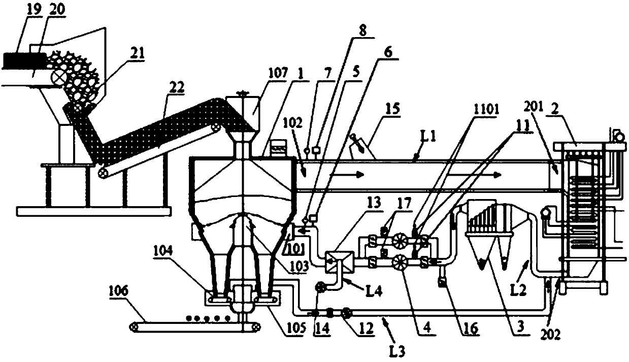
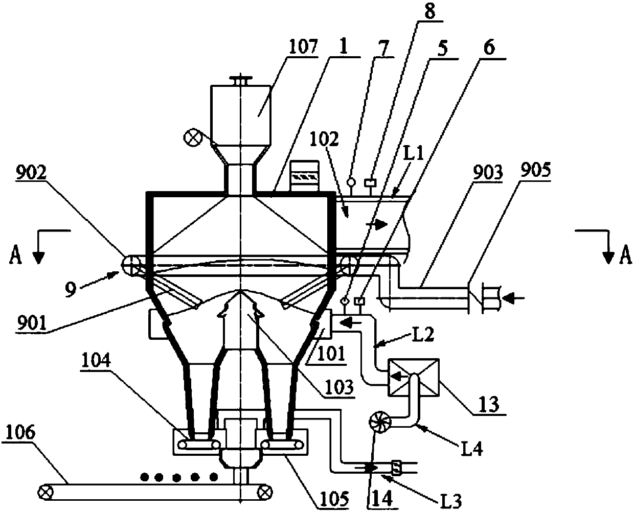
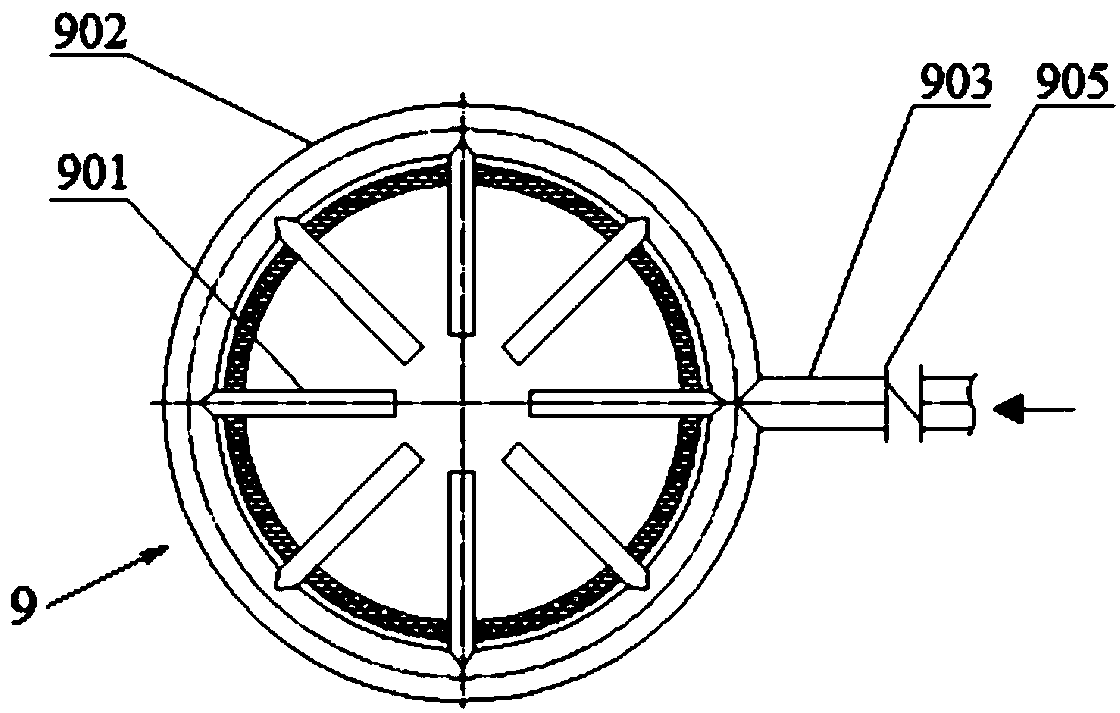
[0192] Such as figure 1 A device for monitoring and controlling residual carbon combustion in the cooling process of hot sintered ore, which includes a vertical cooler 1, a waste heat boiler 2, a dust collector 3 and a circulating fan 4. According to the flue gas flow direction, the high-temperature gas outlet 102 located on the upper part of the tower wall of the vertical cooler 1 is connected to the air inlet 201 of the waste heat boiler 2 through the first pipe L1. The second pipeline L2 drawn from the air outlet 202 of the waste heat boiler 2 is connected to the low-temperature gas inlet 101 located at the lower part of the tower wall of the vertical cooler 1 via the dust collector 3 and the circulating fan 4 . The low temperature gas inlet 101 communicates with the air supply device 103 at the bottom of the tower body of the vertical cooler 1 . The device is provided with a first temperature measuring device 5 and a first flow rate detecting device 6 at the low temperature...

Embodiment 2

[0201] Such as Figure 2-5 A device for monitoring and controlling residual carbon combustion in the cooling process of hot sintered ore, which includes a vertical cooler 1, a waste heat boiler 2, a dust collector 3 and a circulating fan 4. According to the flue gas flow direction, the high-temperature gas outlet 102 located on the upper part of the tower wall of the vertical cooler 1 is connected to the air inlet 201 of the waste heat boiler 2 through the first pipe L1. The second pipeline L2 drawn from the air outlet 202 of the waste heat boiler 2 is connected to the low-temperature gas inlet 101 located at the lower part of the tower wall of the vertical cooler 1 via the dust collector 3 and the circulating fan 4 . The low temperature gas inlet 101 communicates with the air supply device 103 at the bottom of the tower body of the vertical cooler 1 . The device is provided with a first temperature measuring device 5 and a first flow rate detecting device 6 at the low temper...


PUM

PropertyMeasurementUnit
Outer diameteraaaaaaaaaa

Abstract

The invention relates to a device for monitoring and controlling residual carbon combustion during a hot sintering mineral cooling process. The device for monitoring and controlling residual carbon combustion during the hot sintering mineral cooling process comprises a vertical cooler, a waste heat boiler, a dust collector and a circulating fan. According to an exhaust gas flowing direction, a high-temperature gas outlet located in the upper part of a tower wall of the vertical cooler is connected to an air inlet of the waste heat boiler through a first pipeline; a second pipeline drawn from an air outlet of the waste heat boiler is connected to a low-temperature gas inlet located in the lower part of the tower wall of the vertical cooler through the dust collector and the circulating fan;and the low-temperature gas inlet communicates with an air supply device on the bottom part of a tower body of the vertical cooler. The device for monitoring and controlling residual carbon combustion during the hot sintering mineral cooling process is characterized in that a first temperature measurement device and a first flow detection device are arranged on the low-temperature gas inlet of the vertical cooler, and a second temperature measurement device and a second flow detection device are arranged on the high-temperature gas inlet of the vertical cooler. According to the device for monitoring and controlling residual carbon combustion during the hot sintering mineral cooling process provided by the invention, whether secondary combustion occurs on residual carbon during the hot sintering mineral cooling process or not can be accurately judged, and meanwhile, secondary combustion on the residual carbon is effectively controlled through a nitrogen spraying device.

Description

technical field [0001] The invention relates to a device and a method for monitoring residual carbon combustion of hot sintered ore, in particular to a device and method for monitoring and controlling residual carbon combustion of hot sintered ore during cooling, and belongs to the field of sintered ore production in the iron and steel industry. Background technique [0002] The sustainable use of energy is of great importance to the survival and development of human beings, and it is one of the most important social issues facing all countries in the world. With the gradual optimization of the production process of the iron and steel industry and the continuous reduction of process energy consumption, recycling the waste heat and energy of each production process has become one of the most effective ways for iron and steel enterprises to save energy and reduce emissions. The waste heat resources carried by 1 ton of sinter ore in large and medium-sized iron and steel enterpr...

Claims


Application Information

Patent Timeline
IPC IPC(8): F27D15/02F27D17/00F27D19/00F27D21/00
CPCF27D15/0286F27D17/004F27D19/00F27D21/00F27D2017/006F27D2019/0018F27D2019/0043F27M2003/04Y02P10/25
Inventor 向锡炎周浩宇贺新华
Owner ZHONGYE-CHANGTIAN INT ENG CO LTD
Why Eureka
Try Eureka