TLM microstructure for a GPU hardware line rasterization boundary algorithm

A rasterization and boundary technology, applied in computing, special data processing applications, instruments, etc., can solve the problem of high cost of verification and debugging, solve the problem of inaccurate linear rasterization, and help RTL design and development

Active Publication Date: 2019-04-19
XIAN AVIATION COMPUTING TECH RES INST OF AVIATION IND CORP OF CHINA
View PDF7 Cites 6 Cited by
  • Summary
  • Abstract
  • Description
  • Claims
  • Application Information

AI Technical Summary

Problems solved by technology

[0002] In the design and development of graphics processor chips (hereinafter referred to as GPU), the local characteristics of the algorithm, especially the handling of special cases, are easily ignored by RTL designers, and RTL The cost of code verification and debugging is usually relatively high

Method used


Image

  • TLM microstructure for a GPU hardware line rasterization boundary algorithm

Examples


Embodiment

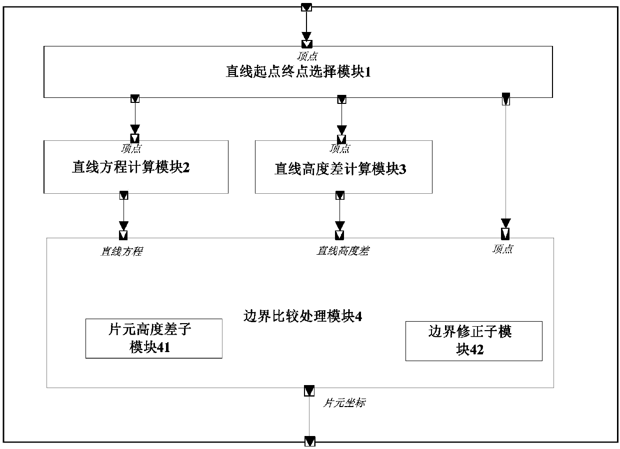
[0044] Below in conjunction with accompanying drawing the present invention is described in further detail, please refer to figure 1 .

[0045] A TLM microstructure for GPU hardware line rasterization boundary algorithm, comprising the following steps:

[0046] 1) Selection of the starting point and end point of the straight line:

[0047] According to the input coordinates of the two end points of the straight line, it is used to select the starting point and end point of the straight line, and also specifies the scanning direction of the straight line from the low point to the high point. When the height of the straight line is the same, the scanning direction is from left to right.

[0048] 2) Calculation of straight line equation:

[0049] From the chosen endpoint and starting point the equation of the line can be calculated: y=kx+b, where k is the slope and b is the intercept.

[0050] 3) Straight line height difference calculation:

[0051] Calculate the maximum heig...


PUM


Abstract

The invention relates to the technical field of computer hardware modeling, and provides a GPU hardware line rasterization boundary algorithm-oriented TLM microstructure, which is characterized in that a straight line starting point and ending point selection module (1) sends a selected starting point and ending point to a straight line equation calculation module (2) and a straight line height difference calculation module (3); The linear equation calculation module (2) carries out linear equation calculation and sends a linear equation to the boundary comparison processing module (4); The straight line height difference calculation module (3) calculates the maximum height difference of a straight line and sends the straight line height difference to the boundary comparison processing module (4); And the boundary comparison processing module (4) receives the linear equation and the linear height difference to perform boundary comparison processing, when the local height difference isgreater than the linear maximum height difference, the height of the sheet element is assigned as the final height, otherwise, the height is kept. And scanning the complete straight line, and calculating the coordinate of each chip element on the straight line.

Description

technical field [0001] The invention relates to the technical field of computer hardware modeling, in particular to a TLM microstructure oriented to GPU hardware line rasterization boundary algorithm. Background technique [0002] In the design and development of a graphics processor chip (hereinafter referred to as GPU), the local characteristics of the algorithm, especially the handling of special cases, are easily ignored by RTL designers, and the cost of verification and debugging of RTL codes is usually relatively high. Therefore, before the RTL design, the algorithm should be verified as early as possible, and the handling of special cases should be comprehensive and accurate. Therefore, the implementation and verification of the algorithm using the algorithm hardware TLM microstructure can provide a reference for RTL design. Contents of the invention [0003] Based on the problems existing in the background technology, a TLM microstructure oriented to GPU hardware l...

Claims


Application Information

Patent Timeline
Patent Type & Authority Applications(China)
IPC IPC(8): G06F17/50
CPCG06F30/398Y02D10/00
Inventor 陈佳姜丽云吴晓成张少锋楼晓强张骏
Owner XIAN AVIATION COMPUTING TECH RES INST OF AVIATION IND CORP OF CHINA
Why Eureka
Try Eureka