Mechanical arm tail end camera hand-eye calibration method and system

A technology of hand-eye calibration and robotic arm, which is applied in the directions of manipulators, program-controlled manipulators, image data processing, etc., which can solve the problems of space conversion relationship, difficult measurement, and unsolved hand-eye relationship calibration.

Inactive Publication Date: 2019-04-19
BEIJING INST OF RADIO MEASUREMENT
View PDF4 Cites 50 Cited by
  • Summary
  • Abstract
  • Description
  • Claims
  • Application Information

AI Technical Summary

Problems solved by technology

The relative conversion relationship between the camera and the end of the manipulator is often determined for applications where the camera is installed at the end of the manipulator, but the spatial conversion relationship is difficult to measure
[0003] The Chinese invention patent (application number 201711038822.9) titled "hand-eye calibration method for a single camera at the end of a mechanical arm" discloses a hand-eye calibration method installed at the end of a mechanical arm, which mainly solves the calibration of the hand-eye relationship under the rotational movement of the end of the mechanical arm in the plane. Project the coordinates of the end of the manipulator to the pixel coordinates. This patent does not solve the problem of hand-eye relationship calibration from the camera to the end of the manipulator when the end has both rotation and translation motions in space.

Method used


Image

  • Mechanical arm tail end camera hand-eye calibration method and system
  • Mechanical arm tail end camera hand-eye calibration method and system
  • Mechanical arm tail end camera hand-eye calibration method and system

Examples


Embodiment Construction

[0021] In order to make the technical solutions and advantages in the embodiments of the present application clearer, the exemplary embodiments of the present application will be further described in detail below in conjunction with the accompanying drawings. Apparently, the described embodiments are only part of the embodiments of the present application, and Not an exhaustive list of all embodiments. It should be noted that, in the case of no conflict, the embodiments in the present application and the features in the embodiments can be combined with each other.

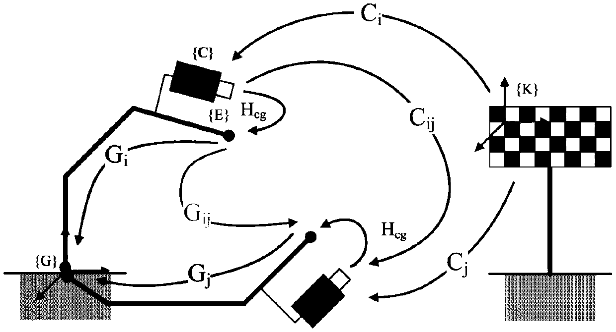
[0022] The core idea of ​​this solution is to calibrate the camera using images in different positions of the robotic arm, and constrain the hand-eye relationship according to multiple spatial relative positions; further, in the process of solving the hand-eye matrix, the hand-eye matrix is ​​divided into rotation and translation The two parts are solved separately, the rotation part is calculated first, and then t...


PUM


Abstract

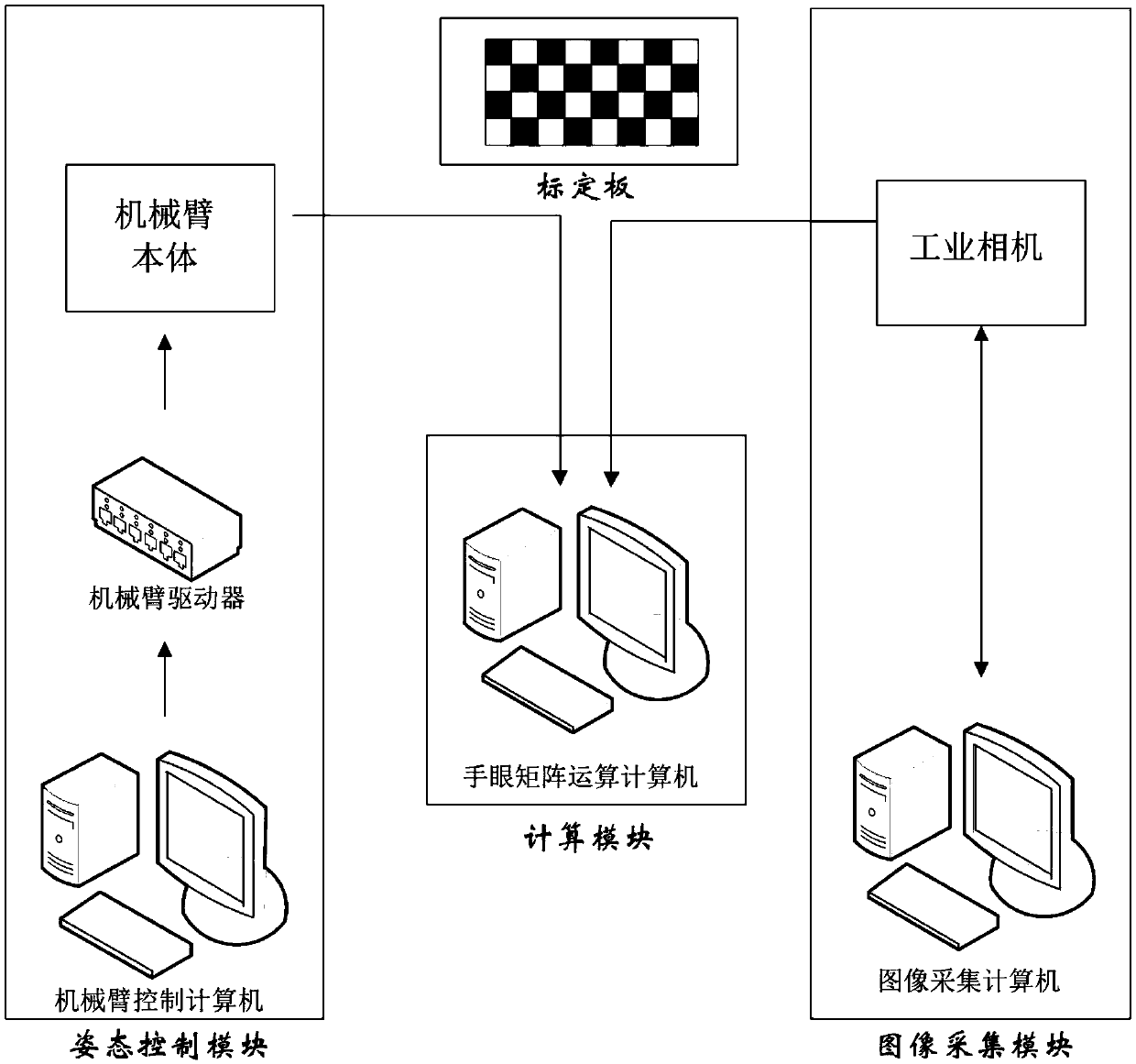
The embodiment of the invention provides a mechanical arm tail end camera hand-eye calibration method and system, and the method comprises the steps: obtaining a calibration image collected by a calibration area when a mechanical arm performs translation and rotation for multiple times at the same time; Obtaining a hand-eye calibration matrix based on the mechanical arm pose information and the calibration image external parameter information; And calibrating the hand-eye relationship of the tail end of the mechanical arm by using the hand-eye calibration matrix. According to the scheme, the calibration of the camera is completed by utilizing spatial motion and image acquisition at a plurality of different positions; According to the principle that the hand-eye relationship is constrainedby multiple spatial relative positions, only the positions of at least three spatial positions relative to the base and external parameters of the camera need to be obtained in the calibration process, and the calibration process can be universal for different mechanical arm models, the number of freedom degrees and camera models; According to the scheme, translation and rotation matrix transformation is utilized, the mechanical arm tail end coordinates are projected to the pixel coordinates, and calibration of the hand-eye relation between the camera and the mechanical arm tail end when the mechanical arm tail end has rotation and translation movement at the same time is obtained.

Description

technical field [0001] The present application relates to the field of solving the space attitude of a manipulator, in particular to a method and system for hand-eye calibration of a camera at the end of a manipulator. Background technique [0002] With the rapid development of computer technology and digital image processing, machine vision has been widely used in scientific research, industrial control and national defense construction. Machine vision can be used as the main means for industrial manipulators to obtain external environmental information, thereby improving the flexibility, intelligence and automation of industrial production. Establishing the corresponding relationship between image pixel coordinates and spatial position coordinates through camera calibration is a key link in the application of machine vision in the field of robotics, and it is also the basis for robotic arms to cooperate with vision to guide actions. According to the camera calibration res...

Claims


Application Information

Patent Timeline
Patent Type & Authority Applications(China)
IPC IPC(8): G06T7/80G06T3/60B25J9/16
CPCB25J9/1653G06T3/60G06T7/80
Inventor 吕泽杉高景一李竹奇李源韩华涛
Owner BEIJING INST OF RADIO MEASUREMENT
Why Eureka
Try Eureka