Indoor robot vision hand-eye relation calibration method based on 3D image sensor

An image sensor and indoor robot technology, applied in the field of robot vision, can solve problems such as complex calculations, achieve high measurement accuracy, simplify the calibration process, and meet the needs of hand-eye calibration

Inactive Publication Date: 2014-07-16
HEFEI INSTITUTES OF PHYSICAL SCIENCE - CHINESE ACAD OF SCI +1
View PDF5 Cites 22 Cited by
  • Summary
  • Abstract
  • Description
  • Claims
  • Application Information

AI Technical Summary

Problems solved by technology

"Robot", 2001, 23(2), pp.113~117) is based on the "black box" idea of ​​directly mapping image coordinates to ...

Method used


Image

  • Indoor robot vision hand-eye relation calibration method based on 3D image sensor
  • Indoor robot vision hand-eye relation calibration method based on 3D image sensor
  • Indoor robot vision hand-eye relation calibration method based on 3D image sensor

Examples


Embodiment Construction

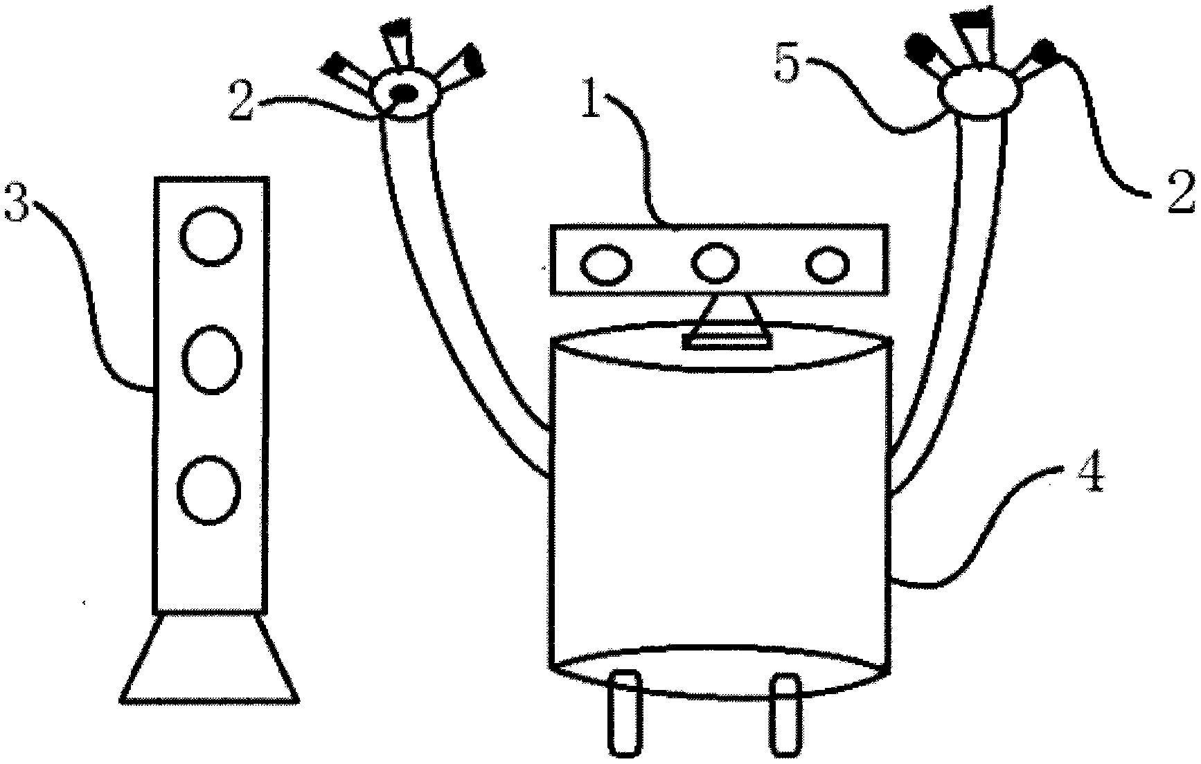
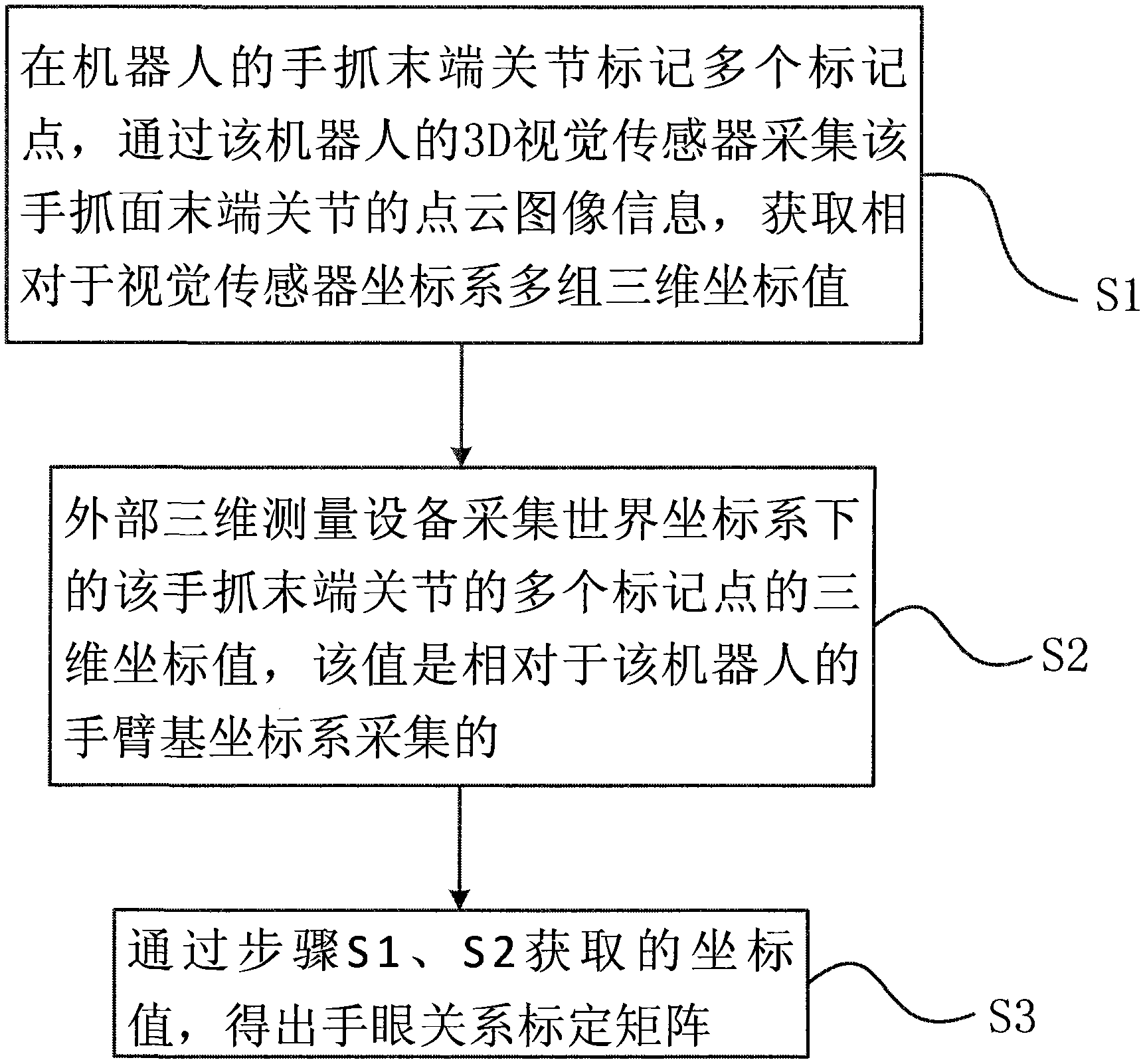
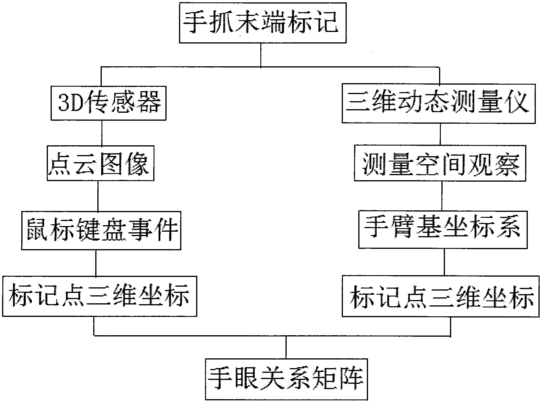
[0015] Please refer to figure 1 , figure 1 It is a schematic diagram of the structure of the robot and the external three-dimensional measuring equipment of the embodiment of the present invention. The indoor mobile robot 4 is provided with a 3D sensor Kinect, and four black dots 2 are marked on the end joint 5 of the robot's hand grasping, as marking points, respectively located at the end of the left and right hand grasping At the end of the three fingers of the joint and in the palm of the hand, an NDI three-dimensional dynamic measuring instrument 3 is erected beside the indoor mobile robot. When measuring, enable the robot to enable the joints of the arm and the end of the hand, so that the end of the hand is in a suitable position in front of the robot, ensure that it is within the field of view of Kinect, and make the four marking points at the end of the finger related to each other as three points Four points that are not collinear are not coplanar. The robot termin...


PUM


Abstract

The invention provides an indoor robot vision hand-eye relation calibration method based on a 3D image sensor. The method comprises the following steps: S1, marking a plurality of marking points on hand grabbing tail end joints of a robot, acquiring point cloud image information of the hand grabbing tail end joints through the 3D vision sensor of the robot, and acquiring a plurality of sets of three-dimensional coordinate values relative to a visual sensor coordinate system; S2, acquiring the three-dimensional coordinate values of the multiple marking points of the hand grabbing tail end joints under the world coordinate system through an external three-dimensional measurement device, wherein the values are acquired through an arm-base coordinate system of the robot; S3, acquiring the coordinate values through the step S1 and the step S2 and obtaining a hand-eye calibration array. The indoor robot vision hand-eye relation calibration method based on the 3D image sensor simplifies the calibration process, the measurement precision is high, and the requirement for indoor robot hand-eye calibration can be effectively met.

Description

technical field [0001] The invention relates to a robot vision method, in particular to an indoor robot vision hand-eye relationship calibration method based on a 3D image sensor. Background technique [0002] With the application and development of 3D sensors, more and more robots use 3D sensors as the robot vision system. Unlike the traditional binocular vision system, the 3D sensor collects the point cloud image information of the current scene, and its image information is a large amount. The three-dimensional coordinate value can intuitively reflect the depth and image information. The traditional binocular vision system uses two industrial cameras to collect the plane image of the current scene. The image information is the pixel value. The depth information is calculated through the parallax of the two images, which will inevitably lead to calculation errors. , leading to a decrease in accuracy. In the robot hand-eye calibration system, the 3D sensor is used to retu...

Claims


Application Information

Patent Timeline
IPC IPC(8): G01B11/00
Inventor 孔令成赵江海张志华张强
Owner HEFEI INSTITUTES OF PHYSICAL SCIENCE - CHINESE ACAD OF SCI
Why Eureka
Try Eureka