System and method for automatic hand-eye calibration of vision system for robot motion

a technology of robot motion and automatic hand-eye calibration, which is applied in the field of machine vision systems, can solve the problems of limiting the speed, accuracy and/or robustness of the calibration process, and achieve the effect of reducing the separation distan

Pending Publication Date: 2020-07-30
COGNEX CORP
View PDF6 Cites 22 Cited by
  • Summary
  • Abstract
  • Description
  • Claims
  • Application Information

AI Technical Summary

Benefits of technology

[0005]This invention overcomes disadvantages of the prior art by providing a system and method that automatically decides motion parameters of hand-eye calibration, and conducts the calibration procedure with minimal human intervention. More particularly, the system and method automatically computes hand-eye calibration motion parameters and spatial positions during pre-calibration, whereby the calibration pattern can continuously (always) remain / be maintained inside, and covering, the entire field of view FOV of the vision system camera, providing a fully automatic hand-eye calibration process. This system and method advantageously operates in a robot-based hand-eye calibration environment and can compensate for a cantilever effect between the calibration target and the FOV. A hand-eye calibration computes the transformation from the robot coordinate space to the camera coordinate space. This generally avoids a need to manually move (by the user) the robot through a set of spatial positions in which the camera then acquires images and locates calibration features on the object at each position to establish the relationship (spatial transformation) between the robot and camera.
[0006]In an illustrative embodiment, a system and method for performing hand- eye calibration of a vision system operating in conjunction with a robot manipulator is provided, wherein there exists relative motion between a calibration object and a field of view (FOV) of a vision system camera. A pre-calibration process performs a three-point calibration in the FOV and computes the rough transformation from a coordinate space of the robot manipulator to a coordinate space of an acquired image of the vision system camera. Based upon the rough transformation, the system and method computes spatial points of features on the calibration object at a plurality of respective locations that are acceptable for performing hand-eye calibration therewith. A hand-eye calibration module then performs hand-eye calibration using the spatial points. Illustratively, the rough transformation is computed based upon an iterative set of motions by the robot manipulator and adjustment of a robot motion step size between the spatial points to maintain features of the calibration object within the field of view and to provide a minimum separation distance between the spatial points. The spatial points can be selected, in part, based upon optional user inputs. In general, it is contemplated that the robot manipulator induces a cantilever effect between the calibration object and the FOV, and the pre-calibration process is arranged to compensate for the cantilever effect. The pre-calibration process, thus, computes the spatial positions so that the calibration object remains in the FOV. In an example, the vision system camera is mounted with respect to, and moves in conjunction with, the robot manipulator. In another example, the calibration object is mounted with respect to, and moves in conjunction with, the robot manipulator. Illustratively, the robot manipulator comprises one of a multi-axis robot and a motion stage. The hand-eye calibration can be performed in a sequence of motion steps that respectively define a motion step size therebetween, and wherein the motion step size is based on at least one of (a) a size of acquired image pixels of the vision system camera and (b) a size of the FOV of the vision system camera as determined from at least one of the images of the calibration object acquired up to a current motion step. The rough transformation can be computed based upon at least one of (a) a three-step motion process, and (b) an iterative set of motions by the robot manipulator with adjustment of a robot motion step size between the spatial points to maintain features of the calibration object within the field of view and to provide a minimum separation distance between the spatial points.

Problems solved by technology

This can limit the speed, accuracy and / or robustness of the calibration process.

Method used


Image

  • System and method for automatic hand-eye calibration of vision system for robot motion
  • System and method for automatic hand-eye calibration of vision system for robot motion
  • System and method for automatic hand-eye calibration of vision system for robot motion

Examples


Embodiment Construction

[0014]I. System Overview

[0015]A. Robot-mounted Camera and Stationary Calibration Object

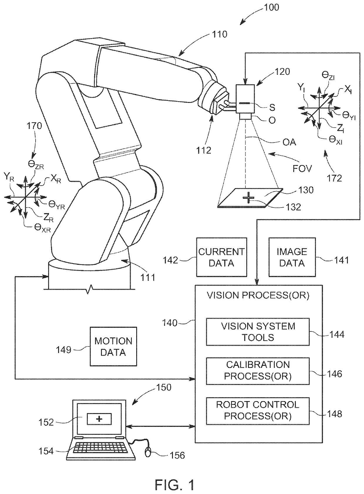
[0016]FIG. 1 shows an robotic manipulator arrangement 100 in which a multi-axis (e.g. six-axis) robot arm 110 is shown on a fixed base 111 with an end effector 112 that is adapted to carry a vision system camera assembly 120. The camera 120 is manipulated around the workspace so that it can direct its optical axis OA and field of view into alignment with a calibration object / plate 130. The object 130 can define any appropriate calibration pattern and associated fiducials—for example crossing lines 132. The camera can be mounted on the end effector 112 in such a manner as to allow it to experience a full range of motion along a plurality of axes. The end effector 112 can also include a manipulator (grippers, suction cup, etc.) to move an object of interest (e.g. a part undergoing alignment or pick-and-place). In this manner, the vision system camera assembly 120 moves in tandem with the end effecto...


PUM


Abstract

This invention provides a system and method that automatically decides motion parameters of hand-eye calibration, and conducts the calibration procedure with minimal human intervention. It automatically computes hand-eye calibration motion parameters and spatial positions during pre-calibration, whereby the calibration pattern can continuously remain inside, and covering, the entire field of view FOV of the vision system camera, providing a fully automatic hand-eye calibration process. This system and method advantageously operates in a robot-based hand-eye calibration environment and can compensate for a cantilever effect between the calibration target and the FOV. A hand-eye calibration computes the transformation from the robot coordinate space to the camera coordinate space. This generally avoids a need to manually move the robot through a set of spatial positions in which the camera then acquires images and locates calibration features on the object at each position to establish the relationship between the robot and camera.

Description

FIELD OF THE INVENTION[0001]This application relates to machine vision systems, and more particularly, to systems and methods for calibrating such systems in conjunction with a robot manipulator.BACKGROUND OF THE INVENTION[0002]In machine vision systems (also termed herein “vision systems”), one or more cameras are used to perform vision system process on an object or surface within an imaged scene. These processes can include inspection, decoding of symbology, alignment and a variety of other automated tasks, such as controlling the motion of a robot arm or motion stage that is used to manipulate and object with respect to one or more degrees of freedom and / or dimensions. More particularly, a vision system can be used to inspect a flat work piece being manipulated within an imaged scene. The scene is typically imaged by one or more vision system cameras that can include internal or external vision system processors that operate associated vision system processes to generate results...

Claims


Application Information

Patent Timeline
Patent Type & Authority Applications(United States)
IPC IPC(8): B25J9/16
CPCB25J9/1692B25J9/1664B25J9/1697B25J9/1653G06T7/80G05B2219/39057B25J9/161B25J9/046B25J19/023
Inventor DRIXLER, BERNHARDHU, YINGCHUAN
Owner COGNEX CORP
Why Eureka
Try Eureka