
Drive circuit, display panels and display device

A technology for driving circuit boards and driving circuits, which is applied to circuits, electrical components, electrical solid-state devices, etc., and can solve problems such as inconsistent signal transmission, reduced display quality of display panels, and uneven brightness of display panels.

Active Publication Date: 2019-04-19
HKC CORP LTD
View PDF8 Cites 6 Cited by
  • Summary
  • Abstract
  • Description
  • Claims
  • Application Information

AI Technical Summary

Problems solved by technology

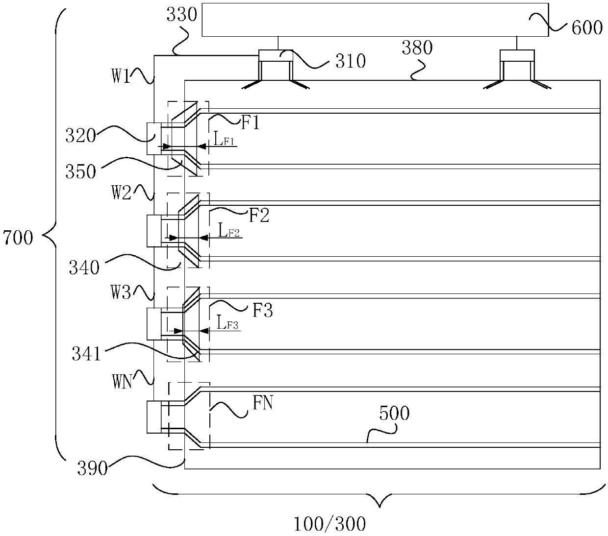
[0003] Since the substrate wiring has a certain resistance value, the resistance of the fan-out line connected to the next gate driver chip will be larger than the resistance value of the fan-out line connected to the previous gate driver chip, so that the signal between adjacent gate driver chips Inconsistent transmission makes the brightness of the display panel uneven and the display quality of the display panel deteriorates

Method used


Image

  • Drive circuit, display panels and display device
  • Drive circuit, display panels and display device
  • Drive circuit, display panels and display device

Examples


Embodiment Construction

[0024] It should be understood that the terminology and specific structural and functional details disclosed herein are representative only for describing specific embodiments, but the application can be embodied in many alternative forms and should not be construed as merely Be limited by the examples set forth herein.

[0025] In the description of the present application, the terms "first" and "second" are used for descriptive purposes only, and cannot be understood as indicating relative importance, or implicitly indicating the quantity of indicated technical features. Therefore, unless otherwise specified, the features defined as "first" and "second" may explicitly or implicitly include one or more of these features; "plurality" means two or more. The term "comprising" and any variations thereof mean non-exclusive inclusion, possible presence or addition of one or more other features, integers, steps, operations, units, components and / or combinations thereof.

[0026] Al...


PUM


Abstract

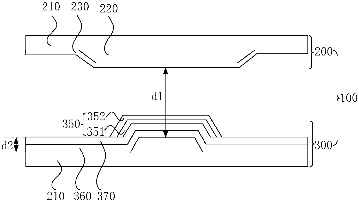
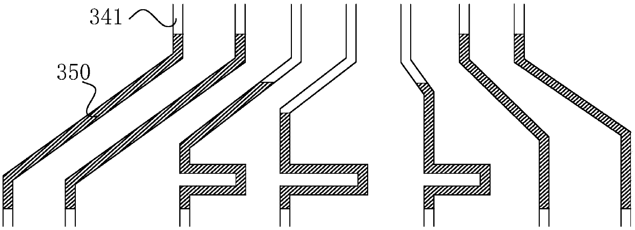
The invention discloses a drive circuit, display panels and a display device. The drive circuit comprises a drive circuit board; a plurality of gate drive chips which are connected with the drive circuit board; a connection line for connection of the drive circuit board and the gate drive chips; fanout lines connected between the gate drive chips and gate lines of the display panel, wherein the fanout lines connected with the same gate drive chip form a fanout area, and the fanout areas are arranged along a transmission direction of signals; and additional conductive film set in the fanout areas, wherein an effective area of the additional conductive film set in each fanout area is different, and the effective areas are reduced one by one starting from the first fanout area. According to the drive circuit, the display panels and the display device, the additional conductive film is added to the fanout areas to form a compensation capacitor, thereby increasing a time constant of signaldelay of a previous fanout area, so the time constant of the signal delay of each fanout area is equal, and the signals of each fanout area are output synchronously.

Description

technical field [0001] The present invention relates to the field of display technology, in particular to a driving circuit, a display panel and a display device. Background technique [0002] With the advancement of science and technology, liquid crystal displays with many advantages such as power saving, no radiation, small size, low power consumption, right-angle plane, high resolution, and stable image quality, especially for various information products such as mobile phones, Products such as notebook computers, digital cameras, PDAs, and LCD screens are becoming more and more popular, which also greatly increases the demand for LCD displays. A liquid crystal display usually includes at least two driver chip connections for transmitting gate drive signals. Two adjacent gate driving chips are also connected through a substrate wire (Wire on Array, WOA). Each gate driver chip is respectively connected to a group of fanout lines (Fanout) on the substrate, and is connecte...

Claims


Application Information

Patent Timeline
IPC IPC(8): G09G3/36
CPCG09G3/36G09G2320/0233H01L27/124G02F1/1345G02F1/13306G02F1/13452G02F1/136286
Inventor 刘忠念
Owner HKC CORP LTD
Learn More