Coupled reactor residual-heat removal system

A reactor and waste heat technology, applied in the field of nuclear reactors, to achieve the effects of improving reliability, ensuring flow, and prolonging idle time

Pending Publication Date: 2019-04-19
CHINA INSTITUTE OF ATOMIC ENERGY
View PDF0 Cites 3 Cited by
  • Summary
  • Abstract
  • Description
  • Claims
  • Application Information

AI Technical Summary

Problems solved by technology

However, for high-power research reactors, the remaining heating power is still considerable, and it is impossible to directly use the above method

Method used


Image

  • Coupled reactor residual-heat removal system
  • Coupled reactor residual-heat removal system

Examples


Embodiment Construction

[0023] In order to make the object, technical solution and advantages of the present invention clearer, the present invention will be further described in detail below in conjunction with specific embodiments and with reference to the accompanying drawings.

[0024] According to the basic idea of ​​the present invention, a coupled reactor waste heat export system is provided. On the basis of the previous research reactor waste heat export technology, according to the safety requirements of the reactor, combined with the characteristics of the design, different types of waste heat discharge means are integrated to form a system. A coupled waste heat removal technology.

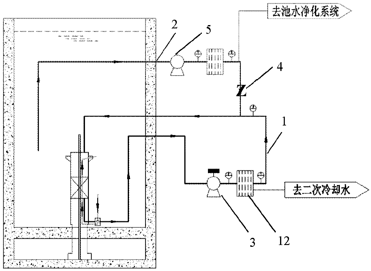
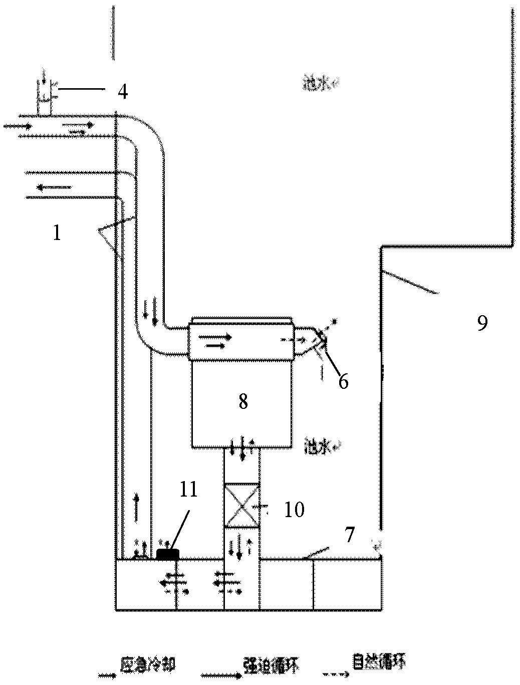
[0025] figure 1 It is a cross-sectional schematic diagram of a coupled reactor waste heat exporting system according to an embodiment of the present invention.

[0026] Such as figure 1 As shown, the reactor waste heat export system of the embodiment of the present invention includes:

[0027] The main cooli...


PUM


Abstract

The invention discloses a coupled reactor residual-heat removal system which comprises a main cooling circuit for driving the liquid in the circuit to flow through a main pump so as to take away the heat of a reactor, an emergency reactor core cooling system configured to operate simultaneously with the reactor and configured with an uninterruptible power supply, a pipeline connected between the main cooling circuit and the emergency reactor core cooling system. An emergency cooling pipeline check valve is arranged on the pipeline to be turned on after the main pump of the main cooling circuitstops power supply. In the coupled residual-heat removal system, the pipeline is arranged between the main cooling circuit and the emergency reactor core cooling system and is provided with the emergency cooling pipeline check valve which is turned on after the main pump of the main cooling circuit stops power supply so that new water flow circulation can still be achieved after the main coolingloop is powered off, and residual heat in a reactor core can be led out.

Description

technical field [0001] The invention relates to the field of nuclear reactors, and further relates to a coupled reactor waste heat exporting system. Background technique [0002] The export of waste heat is an important part of the three major safety functions of nuclear reactors. The cooling flow at each stage is fully adapted to the change of core waste heat, and the flow is excessively smooth. For a long period of time after the shutdown of the nuclear reactor, residual heat is generated due to residual fission and the decay of fission fragments. In the previous design of the residual heat removal system of the pool-type research reactor, since the operating power of the research reactor is only a few MW, the residual heating power It is very small, and the waste heat from the core is basically transferred to the large water pool through natural circulation, and then transferred to the atmosphere through the evaporation of the water pool. However, for high-power research...

Claims


Application Information

Patent Timeline
Patent Type & Authority Applications(China)
IPC IPC(8): G21C15/18
CPCG21C15/18G21C15/182Y02E30/30
Inventor 石永康柯国土袁履正刘天才金华晋刘兴民庄毅张金山黄兴蓉石家娟
Owner CHINA INSTITUTE OF ATOMIC ENERGY
Why Eureka
Try Eureka