Device for cooling at least one battery cell of battery module

A technology for battery modules and battery cells, applied in the direction of batteries, electrical components, secondary batteries, etc., can solve problems such as difficulty in ensuring heat conduction, and achieve the effect of reducing cell aging and improving thermal management.

Pending Publication Date: 2019-04-19
VOLKSWAGEN AG
View PDF5 Cites 0 Cited by
  • Summary
  • Abstract
  • Description
  • Claims
  • Application Information

AI Technical Summary

Problems solved by technology

Furthermore, it is difficult to ensure heat conduction downwards in the direction of the bottom of the housing in the battery module itself

Method used


Image

  • Device for cooling at least one battery cell of battery module
  • Device for cooling at least one battery cell of battery module
  • Device for cooling at least one battery cell of battery module

Examples


Embodiment Construction

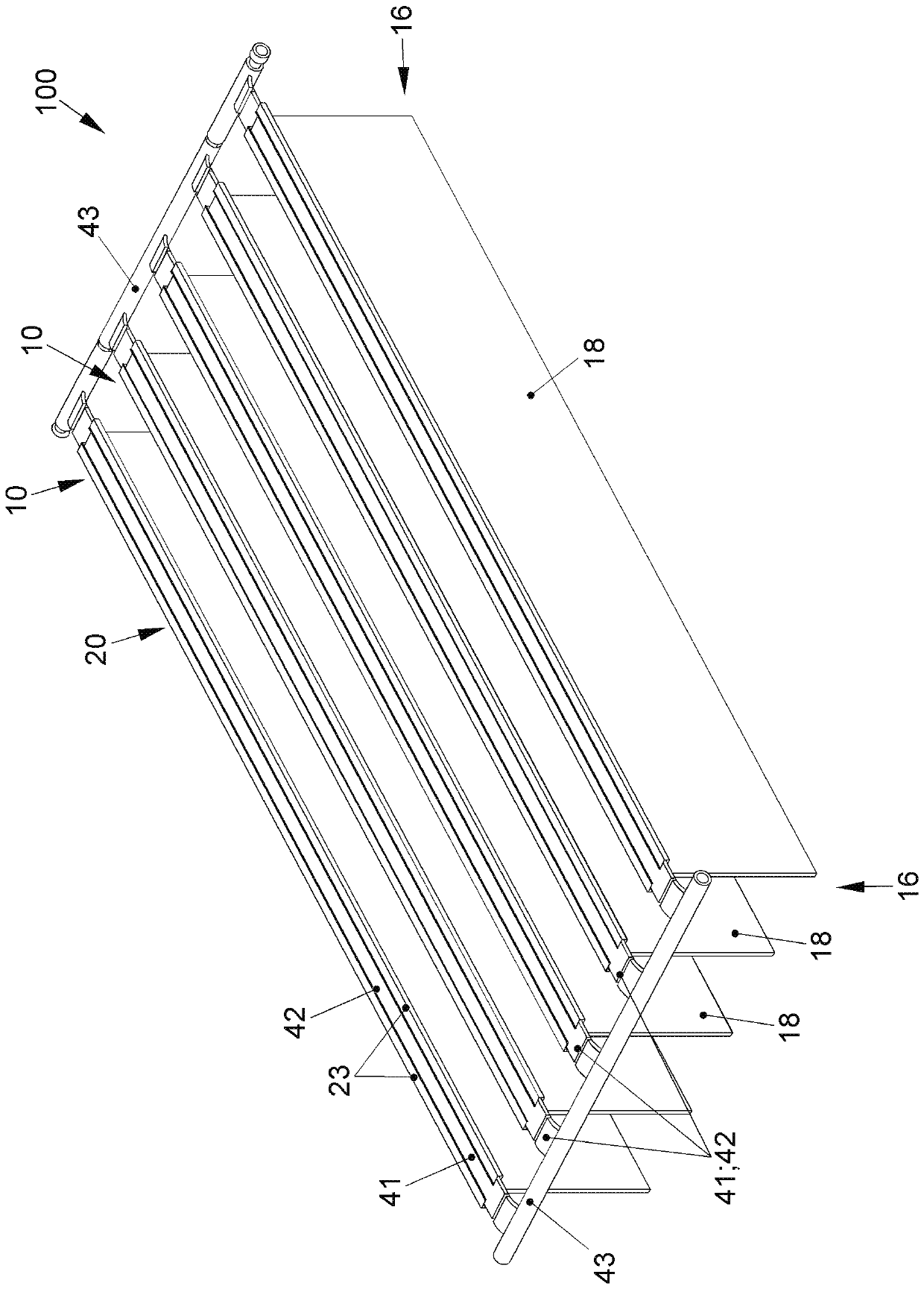
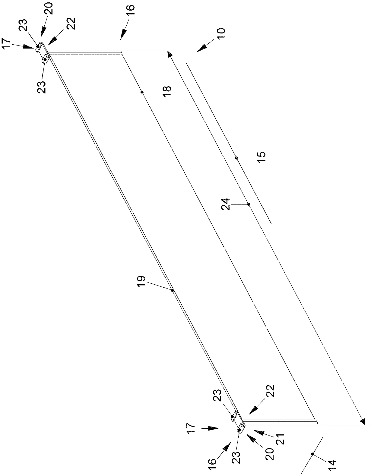
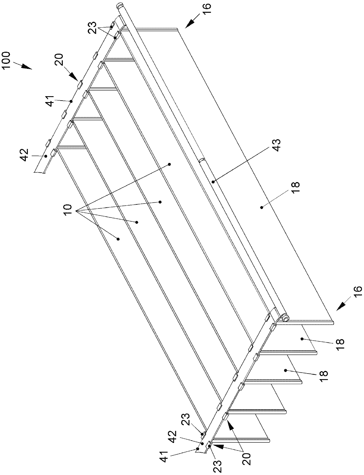
[0055] figure 1 Shown is a heat transfer element (10) of a device (100) for cooling at least one battery cell (201) of a battery module (200). The heat transfer element (10) is designed flat. Furthermore, the heat transfer element (10) is configured plate-shaped and has a longitudinal direction (15) and a thickness direction (14). The heat transfer element (10) is configured to be compressible in the thickness direction (14). The heat transfer element (10) can thus be squeezed together in the thickness direction (14).

[0056] The heat transfer element ( 10 ) has two flat sides ( 18 ), which can be arranged in such a way that they each rest on the flat sides of the battery cells ( 201 ) of the battery module ( 200 ). Thereby, the volume expansion of the battery cell (201) due to the compression of the heat transfer element (10) in the thickness direction (14) can be balanced.

[0057] The heat transfer element (10) has two longitudinal ends (16), wherein in the corner regi...


PUM


Abstract

The invention relates to a device (100) for cooling at least one battery cell (201) of a battery module (200), wherein the device (100) comprises a plate-shaped heat transfer element (10), and the device (100) which compensates for expansion of the battery cell (201) of the battery module (200) is formed.

Description

technical field [0001] The invention relates to a device for cooling at least one battery cell of a battery module according to claim 1 and to a battery module according to claim 9 . Background technique [0002] It is basically known to provide a cooling device for a high-voltage battery in order to dissipate the heat formed during charging or discharging on the one hand and to generate as constant a temperature as possible within the battery on the other hand. and balanced temperature, and thus resist aging of the battery cells. A cooling device of this type is typically implemented via the housing bottom of the battery module below which the cooling device is arranged. However, the thermal transfer to the cooling device located below the housing bottom of the battery module housing must be ensured in a complex manner using thermal paste. Furthermore, it is difficult to ensure heat conduction downwards in the direction of the housing bottom in the battery module itself. ...

Claims


Application Information

Patent Timeline
IPC IPC(8): H01M10/655H01M10/6555H01M10/6557H01M10/6556H01M50/211H01M50/291
CPCH01M10/655H01M10/6555H01M10/6556H01M10/6557H01M50/291H01M50/211H01M2220/20H01M10/625H01M10/647H01M10/6552H01M10/613Y02E60/10
Inventor K.沃林U.帕布斯特T.施特勒莱因K.博尔内曼H.赫滕V.霍姆C.博克尔曼-格罗特芬德
Owner VOLKSWAGEN AG
Why Eureka
Try Eureka