Girder drilled template tooling and steel box bond beam drilling method

A technology of steel beams and templates, applied in the direction of drilling dies for workpieces, etc., can solve the problems of difficulty in guaranteeing connection accuracy, inability to meet the manufacturing accuracy of curved steel bridges, and connection accuracy requirements of hole groups, etc., achieving strong practicability and satisfying Manufacturing rule requirements, the effect of improving efficacy

Pending Publication Date: 2019-04-23
CHINA RAILWAY BAOJI BRIDGE GRP
View PDF0 Cites 5 Cited by
  • Summary
  • Abstract
  • Description
  • Claims
  • Application Information

AI Technical Summary

Problems solved by technology

It is difficult to guarantee the connection accuracy of the hole group of the rod
[0004] The existing technology can no longer meet the requirements of the manufacturing accuracy of the curved steel bridge and the connection accuracy of the hole group

Method used


Image

  • Girder drilled template tooling and steel box bond beam drilling method
  • Girder drilled template tooling and steel box bond beam drilling method
  • Girder drilled template tooling and steel box bond beam drilling method

Examples


Embodiment Construction

[0023] The following will clearly and completely describe the technical solutions in the embodiments of the present invention with reference to the accompanying drawings in the embodiments of the present invention. Obviously, the described embodiments are only some, not all, embodiments of the present invention. Based on the embodiments of the present invention, all other embodiments obtained by persons of ordinary skill in the art without making creative efforts belong to the protection scope of the present invention.

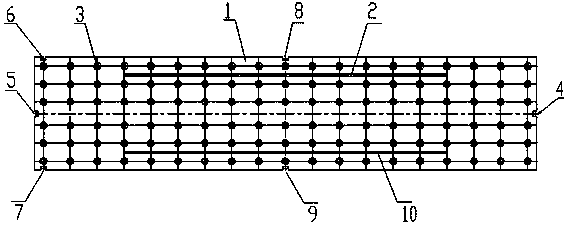
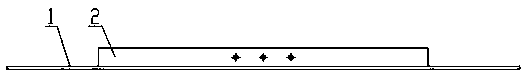
[0024] see Figure 1-4 , the invention provides a technical solution: a steel beam drilling sample tooling, including a cover panel 1, the cover panel 1 is a rectangular plate, and the surface of the cover panel 1 is provided with drilling sleeves arranged in a rectangular array 3. The surface of the covered panel 1 is fixed with a first stiffening plate 2 and a second stiffening plate 10, and the four sides of the covered panel 1 are provided with a first pai...


PUM


Abstract

The invention discloses a girder drilled template tooling. The tooling comprises a rectangular overlay panel. Drilling sleeves arranged in rectangular arrays are arranged on the surface of the overlaypanel. A first reinforcing plate and a second reinforcing plate are fixed to the surface of the overlay panel. A first alignment groove, a second alignment groove, a third alignment groove, a fourthalignment groove, a fifth alignment groove, a sixth alignment groove and the second reinforcing plate are formed in or arranged on the four sides of the overlay panel correspondingly. The first alignment groove is located in a width side of the overlay panel. The second alignment groove is located in the other width side of the overlay panel. The third alignment groove and the fifth alignment groove are located in one length side of the overlay panel. The fourth alignment groove and the sixth alignment groove are located in the other length side of the overlay panel. By means of the girder drilled template tooling, requirements for manufacturing precision, hole group connecting precision and the like of curved steel bridges can be met.

Description

technical field [0001] The invention relates to the technical field of steel box combined beam hole making, in particular to a steel beam drilling model tooling and a steel box combined beam hole making method. Background technique [0002] At present, in the development of urban construction, urban steel bridges are generally built on rivers, roads and overpasses, overpasses and pedestrian bridges where roads cross highways and railways. It meets the needs of urban transportation and residents' travel, taking into account the requirements of aesthetics and flood control. [0003] Steel girder and steel cap beam technology of curved steel-concrete combined bridge. Steel girders are divided into two structural forms: steel box composite beam and steel plate composite beam. The alignment and structure of this type of steel bridge are extremely complex, and the cross-section is a variable cross-section structure. The bottom plate and web plate connection between the steel ma...

Claims


Application Information

Patent Timeline
Patent Type & Authority Applications(China)
IPC IPC(8): B23B47/28B23P15/00
CPCB23B47/28B23P15/00
Inventor 梁晶李军平张海峰薛宏强樊昕哲张鹏李太阳
Owner CHINA RAILWAY BAOJI BRIDGE GRP
Why Eureka
Try Eureka