Robot dynamics parameter identification method and device, terminal device and storage medium

A technology of dynamic parameters and identification methods, applied in manipulators, program-controlled manipulators, manufacturing tools, etc., can solve the problems of low identification accuracy of dynamic parameters, achieve the effect of improving identification accuracy and avoiding error accumulation

Active Publication Date: 2019-04-23
SHENZHEN YUEJIANG TECH CO LTD
View PDF5 Cites 4 Cited by
  • Summary
  • Abstract
  • Description
  • Claims
  • Application Information

AI Technical Summary

Problems solved by technology

[0004] In view of this, the embodiment of the present application provides a robot dynamic parameter identification method, device, terminal equipment and computer-readable storage medium to solve the problem of low accuracy of the existing dynamic parameter identification

Method used


Image

  • Robot dynamics parameter identification method and device, terminal device and storage medium
  • Robot dynamics parameter identification method and device, terminal device and storage medium
  • Robot dynamics parameter identification method and device, terminal device and storage medium

Examples


Embodiment 1

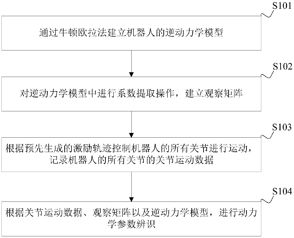
[0073] See figure 1 , is a schematic flow diagram of a method for identifying robot dynamics parameters provided in an embodiment of the present application, and the method may include the following steps:

[0074] Step S101, establishing an inverse dynamics model of the robot through the Newton-Euler method.

[0075] Specifically, the above inverse dynamics model can be specified as Among them, τ j =τ m -τ ext , τ m is the torque of the robot joint servo motor, τ ext is the external moment, M is the robot inertia matrix, C is the Coriolis centrifugal force matrix, G is the gravity, F is the friction force, q is the joint position, is the joint velocity, is the joint acceleration.

[0076] It can be understood that the process of establishing the inverse dynamics model by the Newton-Euler method is well known to those skilled in the art, and will not be repeated here.

[0077] Step S102 , extracting coefficients from the inverse dynamics model to establish an obs...

Embodiment 2

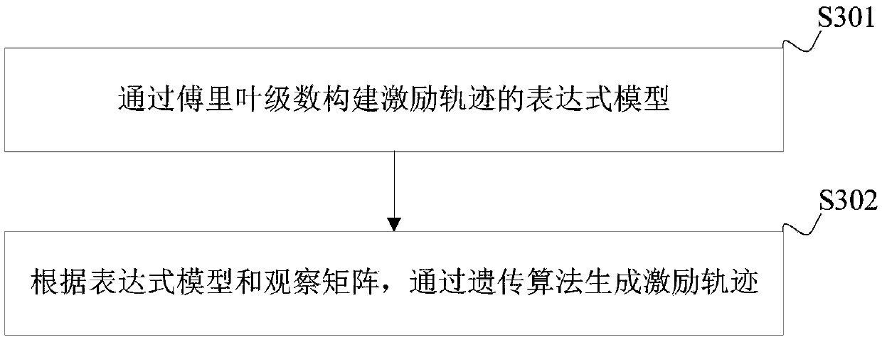
[0102] The excitation trajectory in the first embodiment above may be pre-generated, and the generation method of the excitation trajectory may be any existing method. However, in the process of identifying the parameters of the excitation trajectory generated by the existing method, the problem of the universality of the identification data will be encountered. For example, if the data used in the identification process only includes velocities within the range of 30° / s, then the dynamic model derived from the identified parameters will perform poorly for velocity data above 30° / s. At present, most of the excitation trajectories used in the dynamic parameter identification of robots are constructed by Fourier series, and the acceleration and velocity of the excitation trajectories are generally very small, which cannot cover high acceleration and high velocity areas.

[0103] In order to enable the identified dynamic model to cover areas of high acceleration and high speed, t...

Embodiment 3

[0136] See Figure 5 , which is a schematic structural block diagram of a robot dynamic parameter identification device provided in an embodiment of the present application, the device may include:

[0137] The inverse dynamics model building block 51 is used to establish the inverse dynamics model of the robot by the Newton Euler method;

[0138] The observation matrix building module 52 is used to perform coefficient extraction operations in the inverse dynamics model to establish an observation matrix;

[0139] The joint motion data recording module 53 is used to control all joints of the robot to move according to the pre-generated excitation trajectory, and record the joint motion data of all joints of the robot;

[0140] The identification module 54 is configured to perform dynamic parameter identification according to the joint motion data, the observation matrix and the inverse dynamic model.

[0141] In a feasible implementation manner, the above-mentioned device ma...


PUM


Abstract

The embodiment of the invention is suitable for the technical field of robots, and discloses a robot dynamics parameter identification method and a device, a terminal device and a computer readable storage medium. The method comprises the following steps of establishing an inverse dynamics model of the robot through a newton euler method; performing coefficient extraction operation in the inversedynamics model, establishing an observation matrix; controlling all joints of the robot to move according to the pre-generated excitation trajectory, recording the joint movement data of the related sections of the robot; and carrying out dynamics parameter identification according to the joint movement data, the observation matrix and the inverse dynamics model. According to the embodiment of theinvention, the robot is regarded as a whole to carry out dynamic parameter identification, error accumulation in the single-joint identification process is avoided, and the identification precision of the dynamics parameters is improved.

Description

technical field [0001] The present application belongs to the technical field of robots, and in particular relates to a method, a device, a terminal device, and a computer-readable storage medium for identifying dynamic parameters of a robot. Background technique [0002] Dynamic parameter identification refers to the process of recalculating the dynamic model of the joint or robot based on the data obtained from the encoder and servo motor by obtaining the robot to move according to the command, and obtain the current position, speed, acceleration and torque. [0003] At present, most of the robot dynamics parameters are identified through the motion of a single joint, that is, the identification starts from the last joint, and then gradually pushes forward to the first joint. However, the identification through the movement of a single joint will cause errors in the identification process to accumulate, resulting in inconsistent identification accuracy for each shutdown, r...

Claims


Application Information

Patent Timeline
Patent Type & Authority Applications(China)
IPC IPC(8): B25J9/16
CPCB25J9/1607B25J9/1653B25J9/1671
Inventor 刘培超黄睿朗需林林炯辉曹林攀
Owner SHENZHEN YUEJIANG TECH CO LTD
Why Eureka
Try Eureka