
A manufacturing method for semi-grouting sleeve steel bar joints with precise control of grouting fullness

A semi-grouting sleeve, precise control technology, applied in the direction of construction, building reinforcements, building components, etc., can solve the problems of difficult grouting fullness, difficult to block, different insertion lengths, etc., to achieve good controllability and precise control The effect of grouting fullness and simple operation

Active Publication Date: 2020-11-17
JIANGSU UNIV OF SCI & TECH +1
View PDF6 Cites 0 Cited by
  • Summary
  • Abstract
  • Description
  • Claims
  • Application Information

AI Technical Summary

Problems solved by technology

[0003] However, since the half-grouting sleeve is made of cast steel, it is a connection in a concealed space, and the fullness of grouting cannot be controlled by direct observation, so how to control the fullness of grouting in the production of half-grouting sleeve steel bar joints with different grouting fullness become difficult
[0004] When the volume method is used to control the grouting fullness, it is difficult to calculate the volume of the grouting material under different fullness due to the annular ribs inside the half-grouting sleeve, the irregular surface of the connecting steel bars and the different insertion lengths.
When using the principle of connecting device to determine the fullness of grouting, the fullness is controlled by adjusting the liquid level of the grouting tube at the same height. Since the connecting device needs to be recycled after grouting, it needs to be removed before the grouting material solidifies, and it is difficult to remove it in time Blockage, easy to cause errors

Method used


Image

  • A manufacturing method for semi-grouting sleeve steel bar joints with precise control of grouting fullness
  • A manufacturing method for semi-grouting sleeve steel bar joints with precise control of grouting fullness
  • A manufacturing method for semi-grouting sleeve steel bar joints with precise control of grouting fullness

Examples


Embodiment Construction

[0025] The present invention will be further described below in conjunction with the accompanying drawings and specific embodiments, so that those skilled in the art can better understand the present invention and implement it, but the examples given are not intended to limit the present invention.

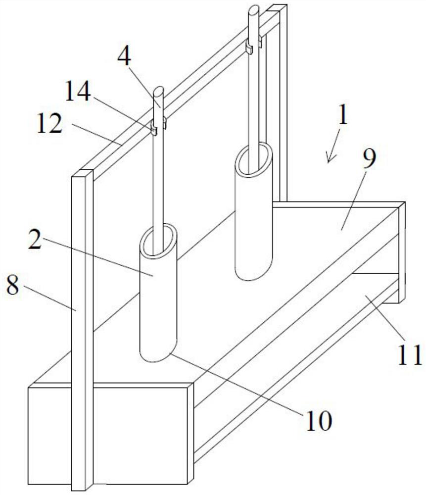
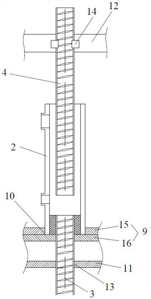
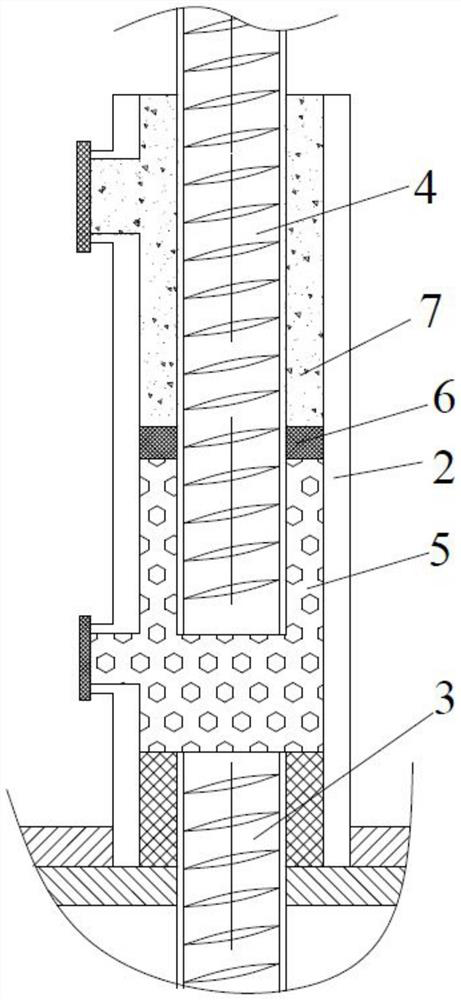
[0026] refer to Figure 1 to Figure 3 As shown, an embodiment of the method for making a half-grouting sleeve steel bar joint that accurately controls the grouting fullness of the present invention includes a supporting fixture 1, a half-grouting sleeve 2, a threaded end connecting steel bar 3, a grouting end connecting steel bar 4, a loose Particles 5, sealing material 6 and grouting material 7 for grouting;

[0027] Specifically, take the semi-grouting sleeve of a certain brand GT14 model as an example to carry out the test. The diameter of the connecting steel bar at the threaded end and the connecting steel bar at the grouting end is 14mm, and the insertion depth of the connec...


PUM


Abstract

The invention discloses a method for manufacturing a semi-grouting sleeve rebar joint for accurately controlling grout plumpness. The semi-grouting sleeve rebar joint comprises a support fixing device, a semi-grouting sleeve, a thread-end connecting rebar, a grout-end connecting rebar, loosing grains and a sealing material. The method comprises the following steps: plugging a slurry outlet and a grouting port of the semi-grouting sleeve, connecting the thread-end connecting rebar with the top of the semi-grouting sleeve, and then reversely mounting on the support fixing device; inserting the grout-end connecting rebar from the center of a sleeve-end rebar insert port on the bottom of the semi-grouting sleeve and mounting on the support fixing device; filling a grout defect area with loosing grains, and then filling the sealing material, grouting and solidifying the grouting material, thereby finishing manufacturing. According to the invention, the grout plumpness can be accurately controlled and the operation is simple and convenient.

Description

technical field [0001] The invention relates to the technical field of prefabricated buildings, in particular to a manufacturing method for half-grouting sleeve steel bar joints that precisely controls the fullness of grouting. Background technique [0002] Semi-grouting sleeve steel bar connection is a commonly used node connection form in prefabricated concrete structures. Due to the late start of domestic prefabricated concrete structures, unskilled on-site personnel, improper operation, etc., the sleeve grouting is not full. Occurs, leaving a safety hazard to the prefabricated concrete structure. In order to study the influence of different grouting fullness on the connection performance of half-grouting sleeve, researchers need to make half-grouting sleeve steel bar joint specimens with different grouting fullness for experimental research. [0003] However, since the half-grouting sleeve is made of cast steel, it is a connection in a concealed space, and the fullness ...

Claims


Application Information

Patent Timeline
Patent Type & Authority Patents(China)
IPC IPC(8): E04C5/16
CPCE04C5/165
Inventor 蒋向于吴玉龙崔咏军金志华李红明顾盛
Owner JIANGSU UNIV OF SCI & TECH
Learn More