projection equipment

A technology of projection equipment and lens cover, which is applied in the optical field, can solve problems such as boot misoperation, affecting heat dissipation, etc., and achieve the effect of improving performance and reliability and good user experience

Active Publication Date: 2021-03-05
APPOTRONICS CORP LTD
View PDF7 Cites 0 Cited by
  • Summary
  • Abstract
  • Description
  • Claims
  • Application Information

AI Technical Summary

Problems solved by technology

[0004] The present invention mainly provides a projection device to solve the problems in the prior art of booting misoperation and affecting heat dissipation

Method used


Image

  • projection equipment
  • projection equipment
  • projection equipment

Examples


Embodiment Construction

[0024] It should be understood that the specific embodiments described here are only used to explain the present invention, not to limit the present invention.

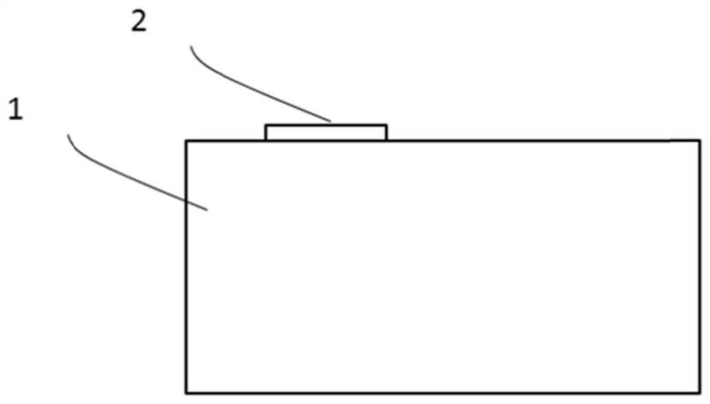
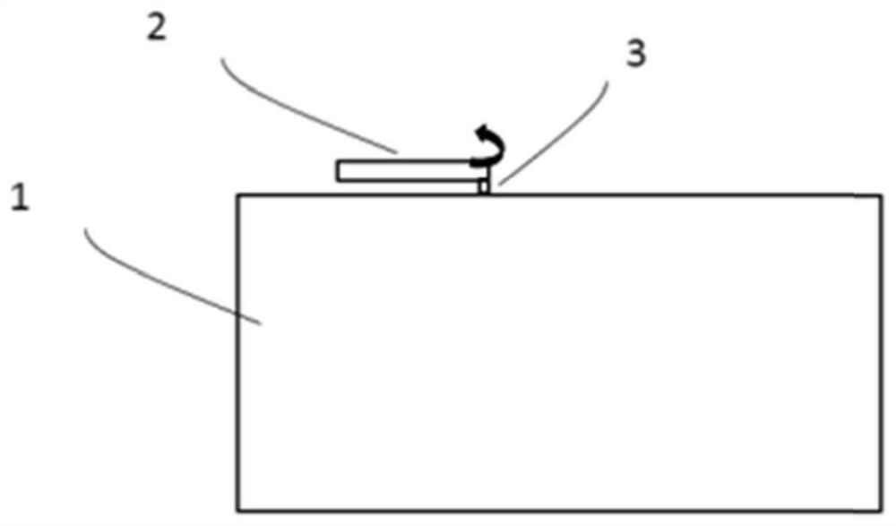
[0025] Such as figure 1 and figure 2 As shown, the projection device of the present invention includes a housing 1 , a lens disposed on the housing 1 , a lens cover 2 covering the lens, and a switch assembly 3 connected to the lens cover 2 .

[0026] The housing 1 is provided with various modules such as an excitation light source, a control module, a light source adjustment system, a main board, and an internal circuit, for realizing the main functions of the projection device. The casing 1 plays a role of protecting the internal structure. The switch assembly 3 plays a role of connecting the lens cover 2 , and the lens cover 2 is connected with the casing 1 through the switch assembly 3 . In addition, the switch assembly 3 also serves as the rotation axis of the lens cover 2 , and the lens cover 2 can rotate wit...


PUM


Abstract

The present invention provides a projection device, including a housing, a lens, a lens cover and a switch assembly, the lens cover can rotate along the switch assembly, the switch assembly has an initial first state and drives the lens cover to stretch in the axial direction In the second state, when the switch assembly is in the second state, the projection device is powered on, and when the switch assembly is in the first state, the projection device is powered off. The projection device with this structure needs to pull out the lens cover and unscrew or translate the lens cover at the same time to realize the power-on function when it is turned on so that it does not block the lens. At the same time, because in the second state, the lens cover and the housing will not fit together, which can avoid the blocking of the heat dissipation port and affect the heat dissipation, improve the performance and reliability of the product, and have a good user experience experience.

Description

technical field [0001] The invention relates to the field of optics, in particular to a miniature projection device. Background technique [0002] At present, miniature projection equipment has been widely welcomed due to its small size and convenience for home and office use. The micro-projection device in the prior art usually adopts the method of turning on the lens cover directly so that it does not block the light outlet. This method of starting up has the possibility of misoperation, especially in the scene of home use, children may turn it on at will. Open the lens cover, if the machine is turned on directly when the child's glasses are staring at the light outlet at this time, it will cause damage to the eyes. In addition, when the lens cover of the current micro-projection device is rotated to the opposite side, it will block the heat dissipation opening and affect the heat dissipation effect. [0003] Therefore, it is necessary to provide a projection device with...

Claims


Application Information

Patent Timeline
Patent Type & Authority Patents(China)
IPC IPC(8): G03B21/14G03B21/16
CPCG03B21/145G03B21/16G03B21/14
Inventor 代尤娜李屹
Owner APPOTRONICS CORP LTD
Why Eureka
Try Eureka