Limiting device for tempered glass transferring

A technology of limiting device and tempered glass, which is applied to conveyor objects, transportation and packaging, furnaces, etc., can solve the problems of glass damage, horizontal and vertical bumps, inconvenience in winding ropes, etc., and achieves the effect of improving safety and flexible design.

Inactive Publication Date: 2019-04-26
安徽友谊钢化玻璃有限公司
View PDF5 Cites 3 Cited by
  • Summary
  • Abstract
  • Description
  • Claims
  • Application Information

AI Technical Summary

Problems solved by technology

[0003] There are certain disadvantages in the use of the existing limiting device for tempered glass transfer. First, when transporting glass, glass transfer racks are often used. During the transport process, there are often horizontal and vertical bumps, which can easily cause glass damage. When dealing with glass of different heights, it is inconvenient to wrap the rope and the safety is not enough

Method used


Image

  • Limiting device for tempered glass transferring
  • Limiting device for tempered glass transferring
  • Limiting device for tempered glass transferring

Examples


Embodiment 1

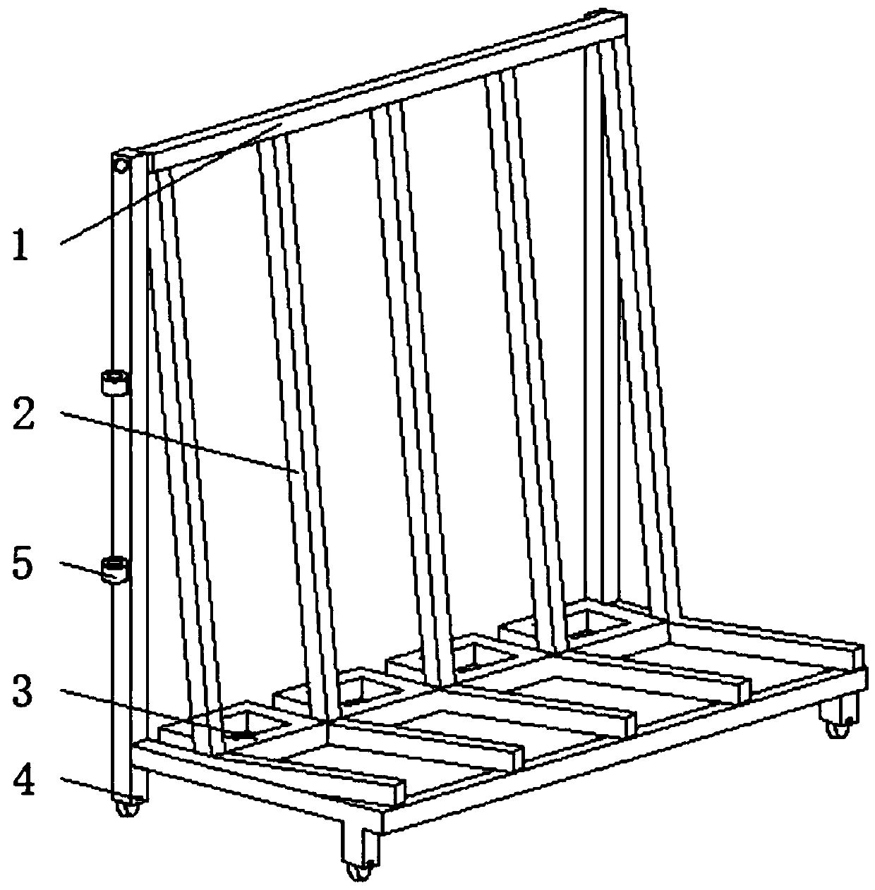
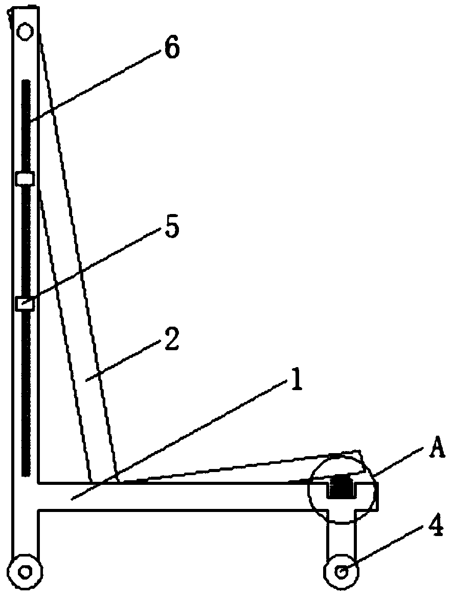
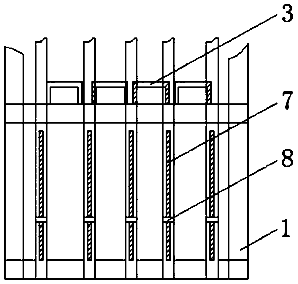
[0028] Such as Figure 1-5 As shown, a limiting device for tempered glass transfer includes a transfer frame 1, and is characterized in that: two of the transfer frame 1 are provided with a first chute 6, and a buckle 5 is installed in the first chute 6, The top of the transfer frame 1 is equipped with a number of L-shaped brackets 2 through the rotating shaft, and the right-angled sides of the L-shaped brackets 2 are connected by welding a number of bottom plates 3, and the angle between the L-shaped bracket 2 and the transfer frame 1 is 15-30° A second chute 7 is provided in the right-angled frame at the bottom of the L-shaped bracket 2, and a stopper 8 is movable embedded in the second chute 7, and an elastic member 14 is installed at the contact position of the right-angled frame with the transfer frame 1; The ring 5 is a hollow cylinder, and the embedded block welded at one end of the clasp 5 slides freely in the first sliding groove 6 .

[0029] The buckle 5 is provided...

Embodiment 2

[0031] Such as Figure 1-5 As mentioned above, a slide bar 11 is installed through the second chute 7, and the surface of the slide bar 11 is fitted with a slide block 10. The top of the top is fixedly installed with a stopper 8 by screws, and the cross section of the stopper 8 is a right triangle.

[0032] The stopper 8 and the slider 10 are set to longitudinally limit the toughened glass placed on the L-shaped bracket. The contact surface between the stopper 8 and the toughened glass is bonded with a sponge pad by superglue for preliminary shock absorption and protection. A compression spring 12 is provided to clamp the tempered glass while limiting the position. The more tempered glass there is on the L-shaped bracket 2, the more the compression spring 12 will compress, so the position-limiting effect will be better. Within the elastic limit, it can More tempered glass is placed, and the design is flexible.

Embodiment 3

[0034] Such as Figure 1-5 As shown, the elastic member 14 is embedded in the L-shaped bracket 2 and corresponds to each L-shaped bracket 2 one by one. The bottom side of one end of the L-shaped bracket 2 is fixed with a washer 13 by a screw, and the washer 13 is closely attached to the elastic member 14. combine;

[0035] Elastic piece 14 is set, if run into road section unevenness in transfer process, cause bump up and down, elastic piece 14 has played buffering effect, avoids that toughened glass vibrates up and down on L-shaped bracket 2 and causes collision, has improved the security of transportation.

[0036] The right-angle inner edge of the L-shaped support 2 is fixedly connected with a rubber pad 9 by screws, and the opening provided by the rubber pad 9 at the top position of the second chute 7 communicates with the second chute 7, and the positions of the rubber pad 9 are all in line with the second chute 7. The tempered glass is in contact, and the transfer increa...


PUM


Abstract

The invention discloses a limiting device for tempered glass transferring. The limiting device for tempered glass transferring comprises a transferring frame, the two sides of the transferring frame are each provided with a first sliding groove, and retaining rings are installed in the first sliding grooves; and a plurality of L-shaped brackets are installed at the top end of the transferring frame through rotation shafts, right-angle sides of the L-shaped brackets are connected in the mode of welding a plurality of bottom plates, an included angle between each L-shaped bracket and the transferring frame is 15-30 degrees, and the right-angle frame at the bottom end of each L-shaped bracket is provided with a second sliding groove. According to the limiting device for tempered glass transferring, the hollow cylindrical retaining rings are arranged and can freely slide in the first sliding grooves, then the positions of the retaining rings are adjusted, tempered glass at different heights can be transversely limited through ropes in the retaining rings, and inclination in the transferring process is avoided; stopping blocks and sliding blocks are arranged to longitudinally limit thetempered glass put on the L-shaped brackets; and meanwhile, springs are arranged, a clamping effect is achieved while the tempered glass is limited, multiple pieces of the tempered glass can be contained within the elastic limit, and design is flexible.

Description

technical field [0001] The invention relates to the field of toughened glass, in particular to a limiting device for transferring toughened glass. Background technique [0002] Tempered glass is safety glass. Tempered glass is actually a kind of prestressed glass. In order to improve the strength of glass, chemical or physical methods are usually used to form compressive stress on the glass surface. Wind pressure, cold and heat, impact, etc., pay attention to distinguish it from FRP. [0003] There are certain disadvantages in the use of the existing limiting device for tempered glass transfer. First, when transporting glass, glass transfer racks are often used. During the transport process, there are often horizontal and vertical bumps, which can easily cause glass damage. When dealing with glass of different heights, it is inconvenient to wind the rope and the safety is insufficient. Contents of the invention [0004] The main purpose of the present invention is to pr...

Claims


Application Information

Patent Timeline
Patent Type & Authority Applications(China)
IPC IPC(8): B65G49/06
CPCB65G49/062
Inventor 李刚
Owner 安徽友谊钢化玻璃有限公司
Why Eureka
Try Eureka