
Novel pushable fork

A kind of fork, a new type of technology, applied in the field of pre-fork, can solve the problems of inconvenient and safe operation, no push structure, large and often work on uneven ground, etc., achieve good use prospects, avoid slipping, and ensure safety.

Inactive Publication Date: 2019-04-26
安徽安鑫货叉有限公司
View PDF9 Cites 4 Cited by
  • Summary
  • Abstract
  • Description
  • Claims
  • Application Information

AI Technical Summary

Problems solved by technology

[0002] According to the connection mode of the fork and the fork frame, it can be divided into two types: hinged and rigid. The tail of the hinged fork has a round hole, which is set on the horizontal axis of the fork frame. This can prevent the fork from being held up by raised obstacles on the ground when the forklift is backing up. The hinged fork is easy to adjust the distance. It is usually used for forklifts with a large lifting capacity and often works on uneven ground. The tail of the fork just connected has a square shape. Hook groove, hooked on the beam of the fork frame, the positioning pin is inserted into the hole of the beam of the fork frame for positioning, and the stopper is used to prevent the fork from falling off. It is usually used for forklifts with small lifting capacity and often operating on flat ground; existing There are certain disadvantages in the use of forks. There is no push-type structure, and it cannot cooperate with the push-pull motor to realize the function of stacking goods, and it has no anti-slip effect. The operation is not convenient and safe enough, and needs further improvement. To a certain extent, we propose a new type of pushable fork

Method used


Image

  • Novel pushable fork
  • Novel pushable fork

Examples


Embodiment Construction

[0016] In order to make the technical means, creative features, goals and effects achieved by the present invention easy to understand, the present invention will be further described below in conjunction with specific embodiments.

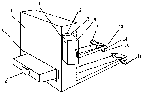
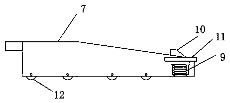
[0017] Such as Figure 1-2 As shown, a new type of pushable fork includes a fork pallet 1, one side of the outer surface of the fork pallet 1 is provided with an accommodating box 2, and the outer surface of the accommodating box 2 is rotatably mounted with fastening screws 3. The fastening screw 3 is rotated and installed on the fork pallet frame 1 and the storage box 2 at the same time. The storage box 2 is fixed and installed with the fork pallet frame 1 through the fastening screw 3, and the inner surface of the storage box 2 is covered with Hinge 4, the outer surface of hinge 4 is fixedly installed with box body door 5, is provided with placement activity opening 6 on the outer wall of pallet fork pallet 1, and placement activity opening 6 is...


PUM


Abstract

The invention discloses a novel pushable fork, comprising a pallet fork plate frame, wherein a containing box body is arranged on the outer surface of one side of the fork plate frame, fastening screws are rotationally arranged on the outer surface of the containing box body, the fastening screws are rotationally arranged on the fork plate frame and the containing box body at the same time, the containing box body is fixedly arranged with the fork plate frame through the fastening screws, a hinge is sleeved on the inner surface of the containing box body, a box body door is fixedly installed on the outer surface of the hinge; a placing movable opening is arranged on the outer wall of the fork plate frame; an additional pushing fork is arranged in the placing movable opening; the outer surface of one side of the additional pushing fork is welded with a hanging plate, a pressure spring is arranged in the additional pushing fork, and a limiter is sleeved on the outer surface of the pressure spring. The novel pushable fork provided by the invention is a push type structure, which can be matched with a push-pull motor to realize the function of stacking goods; and the fork has an anti-slide effect, is convenient to operate and brings better use prospect, etc.

Description

technical field [0001] The invention relates to the field of pre-forks, in particular to a novel pushable fork. Background technique [0002] According to the connection mode of the fork and the fork frame, it can be divided into two types: hinged and rigid. The tail of the hinged fork has a round hole, which is set on the horizontal axis of the fork frame. This can prevent the fork from being held up by raised obstacles on the ground when the forklift is backing up. The hinged fork is easy to adjust the distance. It is usually used for forklifts with large lifting capacity and often working on uneven ground. The tail of the fork just connected has a square shape. Hook groove, hooked on the beam of the fork frame, the positioning pin is inserted into the hole of the beam of the fork frame for positioning, and the stopper is used to prevent the fork from falling off. It is usually used for forklifts with small lifting capacity and often operating on flat ground; existing The...

Claims


Application Information

Patent Timeline
Patent Type & Authority Applications(China)
IPC IPC(8): B66F9/12B66F9/18
CPCB66F9/122B66F9/18
Inventor 何玉柱高锡麟时志平汪文娟
Owner 安徽安鑫货叉有限公司
Learn More