Steel bar planting-free construction method for secondary structure steel bar

A technology of secondary structure and construction method, which is applied in the direction of building structure, formwork/formwork/working frame, and on-site preparation of building components. Inconvenience, large manpower and material resources, etc., to achieve the effect of simple setting of steel bar reservation, reduction of labor for planting bars, and convenient construction

Inactive Publication Date: 2019-04-26
MCC5 GROUP CORP SHANGHAI
View PDF7 Cites 1 Cited by
  • Summary
  • Abstract
  • Description
  • Claims
  • Application Information

AI Technical Summary

Problems solved by technology

[0002] In the construction of the secondary structure, the method of planting reinforcement is usually used to chemically bond the secondary structure and the main structure after the construction of the main structure is completed, but this construction method consumes a lot of manpower and material resources, and its tie strength is not enough satisfactory
[0003] Therefore, there are above-mentioned inconveniences and problems in the construction mode of known chemical mode glued planting bar

Method used


Image

  • Steel bar planting-free construction method for secondary structure steel bar
  • Steel bar planting-free construction method for secondary structure steel bar
  • Steel bar planting-free construction method for secondary structure steel bar

Examples


Embodiment 1

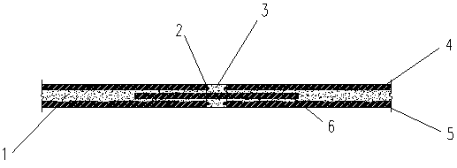
[0023] see now figure 1 , figure 1 A schematic diagram is reserved for the reinforcing bars of the 3-meter-long bottom beam of the embodiment of the present invention.

[0024] a. Formwork support. In the bottom beam 1 with a length of 3 meters, the wooden square 4 at the bottom of the first beam and the wooden square 5 at the bottom of the second beam are respectively 1415 mm long and 50 mm wide, and they are arranged in parallel up and down, and a formwork disconnection position 3 is provided in the middle. In the template disconnection position 3, reserve steel bars 2 are respectively set in the positions of the first beam bottom wooden square 4 and the second beam bottom wooden square 5. Insert a wooden square 6 with a width of 50 mm between the wooden square 4 at the bottom of the first beam and the wooden square 5 at the bottom of the second beam, and the wooden square 6 is parallel to the wooden square 4 at the bottom of the first beam.

[0025] b. Drill holes accord...

Embodiment 2

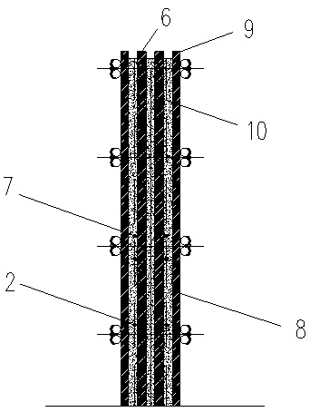
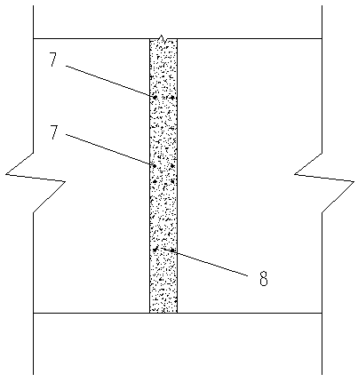
[0032] figure 2 A schematic diagram is reserved for the tie bars at the head plate of the panel wall according to the embodiment of the present invention. For concrete walls with a height greater than 2000mm, square steel 9 templates are supported on both sides of the concrete wall, and steel pipe clamps are used to tighten every 500mm in the height of the concrete wall. Two parallel wooden squares 6 with a certain distance are set between the steel 9 formworks. Set the reserved steel bar 2 at 500mm upward from the foot of the concrete wall, and then set the reserved steel bar 7 for the waist beam at 1000mm upward to complete the supporting formwork and reserved steel bar. image 3 It is the plan view of the reinforcement bars reserved in the middle wall of the formwork according to the embodiment of the present invention, and the distance between the reinforcement bars 7 reserved for two adjacent waist beams is 500mm.

[0033] The remaining steps of this embodiment are the...


PUM


Abstract

The invention discloses a steel bar planting-free construction method for a secondary structure steel bar. The steel bar planting-free construction method is characterized by comprising the followingsteps of a, when a template is erected, performing accurate positioning on a position, calculated according to a drawing, of the secondary structure steel bar, and performing disconnected arrangementof a square timber if necessary; b, drilling a hole according to the position; c, performing template reinforcing; d, inserting the secondary structure steel bar; e, pouring concrete; and f, removinga die to finish secondary structure construction. The steel bar planting-free construction method for the secondary structure steel bar has the advantages that reservation arrangement of the steel barin a secondary structure is simple, construction is convenient, manpower for steel bar planting is greatly reduced, and the binding strength and low engineering cost are ensured.

Description

technical field [0001] The invention relates to a secondary structure construction, in particular to a secondary structure steel bar planting bar-free construction method. Background technique [0002] In the construction of the secondary structure, the method of planting reinforcement is usually used to chemically bond the secondary structure and the main structure after the construction of the main structure is completed, but this construction method consumes a lot of manpower and material resources, and its tie strength is not enough As expected. [0003] Therefore there is above-mentioned inconvenience and problem in the construction method of known chemical mode glue joint planting bar. Contents of the invention [0004] The purpose of the present invention is to propose a secondary structure reinforcement free planting bar construction method in which the secondary structural reinforcement is reserved during the construction of the main structure. [0005] For real...

Claims


Application Information

Patent Timeline
Patent Type & Authority Applications(China)
IPC IPC(8): E04B1/41E04G13/04E04G11/08
CPCE04B1/41E04G11/08E04G11/085E04G13/04
Inventor 杨超
Owner MCC5 GROUP CORP SHANGHAI
Why Eureka
Try Eureka