
Rotating blade underwater dynamic deformation binocular measurement system of composite material propeller model

A technology of composite materials and rotating blades, which is applied in the field of binocular measurement system for underwater dynamic deformation of rotating blades of composite propeller models. Real-time feature relations and other issues

Active Publication Date: 2019-04-26
CHINA SHIP SCIENTIFIC RESEARCH CENTER (THE 702 INSTITUTE OF CHINA SHIPBUILDING INDUSTRY CORPORATION)
View PDF12 Cites 11 Cited by
  • Summary
  • Abstract
  • Description
  • Claims
  • Application Information

AI Technical Summary

Problems solved by technology

However, due to the lower rigidity of composite materials compared with metals, the law of fluid-solid coupling deformation caused by hydrodynamic loads of rotating blades has not been fully grasped. Establish the relationship between the geometry and internal structure of composite blades and the hydrodynamic performance of deformed blades. , has become a key issue in the design and research of composite propellers
At present, the industry still lacks a mature method for measuring the dynamic deformation of composite propeller blades, and cannot grasp the real-time characteristic relationship between composite blade deformation and hydrodynamic performance, and cannot provide a reliable basis for the design of composite propellers.

Method used


Image

  • Rotating blade underwater dynamic deformation binocular measurement system of composite material propeller model
  • Rotating blade underwater dynamic deformation binocular measurement system of composite material propeller model
  • Rotating blade underwater dynamic deformation binocular measurement system of composite material propeller model

Examples


Embodiment Construction

[0032] The specific embodiments of the present invention will be further described below in conjunction with the accompanying drawings.

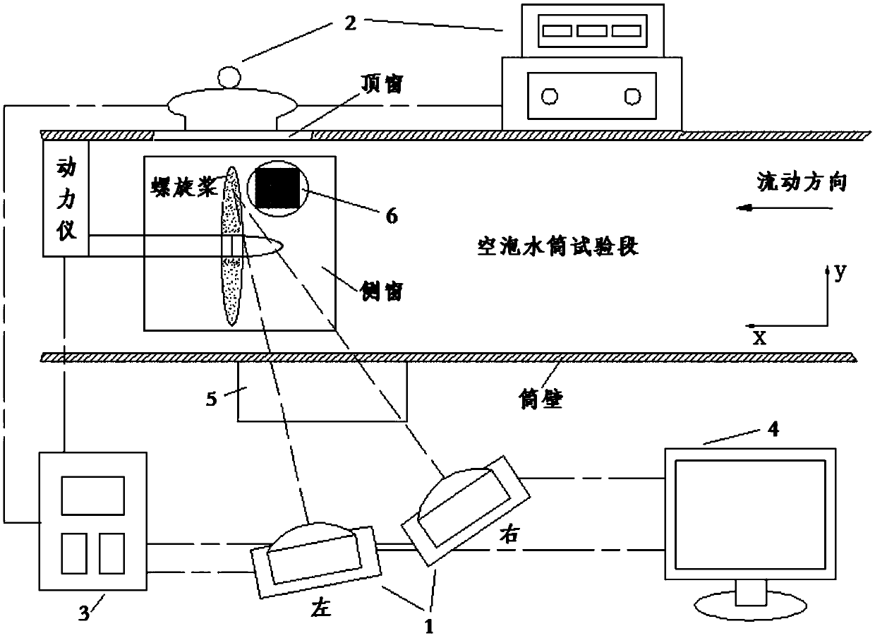
[0033] figure 1 It is a schematic diagram of a composite material propeller model rotating blade underwater dynamic deformation binocular measurement system provided by an embodiment of the present invention, as shown in figure 1 As shown, the measurement system may include: two cameras 1, white light strobe light source equipment 2, synchronizer 3, speckle image acquisition processing and cross-correlation analysis software system 4, optical auxiliary equipment 5, target 6, and dynamic instrument.

[0034] The two cameras are arranged next to the observation window on the side of the cavitation water cylinder test section at about 1 minute, so that the object to be tested can be imaged in the image plane of the two cameras 1 at the same time, and the angle between the optical axes of the two cameras 1 is between 12° and 15°. ° between.

...


PUM


Abstract

The invention discloses a rotating blade underwater dynamic deformation binocular measurement system of a composite material propeller model, and relates to the technical field of propeller testing. The system comprises two cameras, white light stroboscopic light source equipment, a synchronizer, a software system, optical auxiliary equipment, a target and a dynamometer; the two cameras are arranged beside an observation window in the side of a water drum test section; the white light stroboscopic light source equipment is arranged at an observation window in the upper portion of the water drum test section; the synchronizer is connected with the cameras, the software system and the dynamometer and controls synchronous work of the cameras, the software system and the dynamometer; the target is arranged at a to-be-tested area, and the two cameras shoot at least eight pairs of speckle images, at different positions and in different directions, of the target; the software system is in charge of collecting the speckle images and conducting subsequent correlation analysis; the optical auxiliary equipment is arranged on the observation window in the side of the water drum test section. According to the system, through non-contact optical measurement, the speckle images of blades are obtained, real-time deformation features of composite material blades are obtained correlation analysis, and thus guidance in design and optimization of the composite material propeller is achieved.

Description

technical field [0001] The invention relates to the technical field of propeller testing, in particular to a binocular measurement system for underwater dynamic deformation of rotating blades of a composite propeller model. Background technique [0002] Marine composite propeller technology is an emerging propeller material and design technology. Composite propellers have the advantages of light weight, adjustable stiffness and damping, rigid-flexible coupling and self-adaptation. However, due to the lower rigidity of composite materials compared with metals, the law of fluid-solid coupling deformation caused by hydrodynamic loads of rotating blades has not been fully grasped. Establish the relationship between the geometry and internal structure of composite blades and the hydrodynamic performance of deformed blades. , has become a key issue in the design and research of composite propellers. At present, the industry still lacks a mature method for measuring the dynamic de...

Claims


Application Information

Patent Timeline
IPC IPC(8): G01M10/00
CPCG01M10/00
Inventor 薛庆雨武珅宋明太张国平高德宝翟树成周剑
Owner CHINA SHIP SCIENTIFIC RESEARCH CENTER (THE 702 INSTITUTE OF CHINA SHIPBUILDING INDUSTRY CORPORATION)
Learn More