A depth image high-precision restoration method based on boundary capture

A depth image and repair method technology, applied in image enhancement, image analysis, image data processing, etc., can solve problems such as inapplicability of mechanical product assembly scenes, affecting depth image accuracy, and reducing depth image accuracy

Active Publication Date: 2019-04-26
CHONGQING UNIV OF POSTS & TELECOMM
View PDF11 Cites 13 Cited by
  • Summary
  • Abstract
  • Description
  • Claims
  • Application Information

AI Technical Summary

Problems solved by technology

However, the real-time performance of denoising and repairing depth images using methods such as adjacent video frames and convolutional networks is poor. Convolutional networks require a large amount of data sets for supervised learning, and the implementation process is inconvenient. Moreover, it is not suitable for mechanical product assembly scenarios without prior knowledge. not applicable
[0007] Through the above analysis, it can be seen that the existing problems in the field of depth image denoising and repairing are: the method of denoising and repairing based on single-frame depth images is not conducive to image boundary Or the preservation of texture information, affecting the depth image quality
[0008]1) In the existing research, due to the use of filters, the pulsating outlier depth values ​​and large areas of noise in the depth image spread to the surrounding image area, Thus affecting the depth image accuracy
[0009]2) Most of the existing methods will smooth the edge of the object, so that a transition structure appears at the junction of the edge of the object and the background, which reduces the accuracy of the depth image, and the existing noise reduction repair The algorithm takes a long time

Method used


Image

  • A depth image high-precision restoration method based on boundary capture
  • A depth image high-precision restoration method based on boundary capture
  • A depth image high-precision restoration method based on boundary capture

Examples


Embodiment Construction

[0059] The technical solutions in the embodiments of the present invention will be described clearly and in detail below in conjunction with the drawings in the embodiments of the present invention. The described embodiments are only some of the embodiments of the invention.

[0060] The technical scheme that the present invention solves the problems of the technologies described above is:

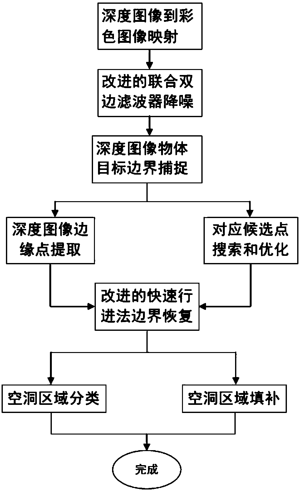
[0061] The present invention proposes a depth image restoration method based on boundary capture with the help of color image information collected by a depth sensor. This method first designs a parallel registration method of depth image and color image, so as to quickly complete the acquisition of the depth value of each pixel in the color image. Secondly, on the basis of the joint bilateral filter, the noise kernel function and the subordinate kernel function are introduced to denoise the depth image, and then the depth image and the color image have similar object boundaries, and the ...


PUM


Abstract

The invention requests to protect a depth image high-precision restoration method based on boundary capture, and the method comprises the following steps: 1, firstly, designing a registration method of a depth image and a color image which are parallel, thereby rapidly completing the obtaining of the depth value of each pixel point in the color image; Step 2, introducing a noise kernel function and a subordinate kernel function on the basis of the united bilateral filter to perform noise reduction on the depth image; Step 3, capturing the boundary of the depth image through the object boundaryof the color image by utilizing the characteristic that the depth image and the color image have similar object boundaries, and obtaining a 'cavity' region at the object boundary of the depth image;And step 4, finally, filling the cavity area through an improved rapid implementation method. According to the method, the edge precision of the depth image can be improved on the premise of ensuringthe real-time performance.

Description

technical field [0001] The invention belongs to the technical field of augmented reality, and in particular relates to a high-precision restoration method for depth images based on boundary capture. Background technique [0002] In recent years, with the development of active ranging sensing technology, it has become possible to use low-cost sensors to obtain high-resolution 3D scene information in real time. Especially along with the coming out of depth sensors such as Kinect, Softkinetic, make this advantage more obvious. They work by emitting continuous near-infrared pulses at the target scene, and then using a sensor to receive the light pulses reflected back by the object. By comparing the phase difference between the emitted light pulse and the light pulse reflected by the object, the transmission delay between the light pulses can be calculated to obtain the distance of the object relative to the emitter, and finally a depth image can be obtained. However, limited b...

Claims


Application Information

Patent Timeline
Patent Type & Authority Applications(China)
IPC IPC(8): G06T5/00G06T7/30G06T7/80
CPCG06T5/002G06T5/005G06T7/30G06T7/80G06T2207/10024
Inventor 王月罗志勇唐文平罗蓉赵杰
Owner CHONGQING UNIV OF POSTS & TELECOMM
Why Eureka
Try Eureka