
Flyback power supply circuit

A flyback power supply and circuit technology, applied to electrical components, adjusting electrical variables, instruments, etc., can solve problems such as poor reliability

Inactive Publication Date: 2019-04-26
GREE ELECTRIC APPLIANCES INC
View PDF7 Cites 0 Cited by
  • Summary
  • Abstract
  • Description
  • Claims
  • Application Information

AI Technical Summary

Problems solved by technology

[0004] Based on this, it is necessary to provide a flyback power supply circuit for the problem of poor reliability of the traditional flyback power supply circuit

Method used


Image

  • Flyback power supply circuit
  • Flyback power supply circuit
  • Flyback power supply circuit

Examples


Embodiment Construction

[0021] In order to facilitate the understanding of the present application, the present application will be described more fully below with reference to the relevant drawings. Preferred embodiments of the application are shown in the accompanying drawings. However, the present application can be embodied in many different forms and is not limited to the embodiments described herein. On the contrary, the purpose of providing these embodiments is to make the understanding of the disclosure of the application more thorough and comprehensive.

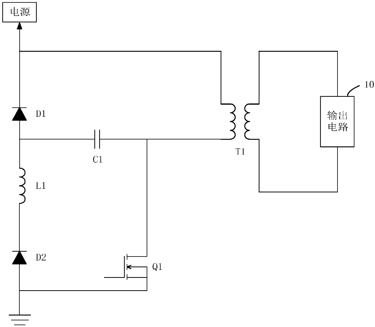
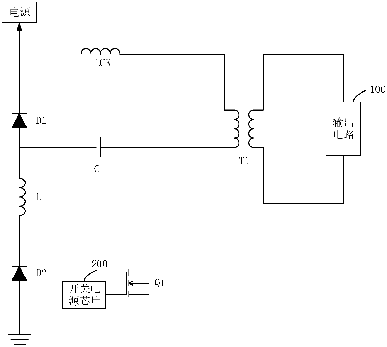
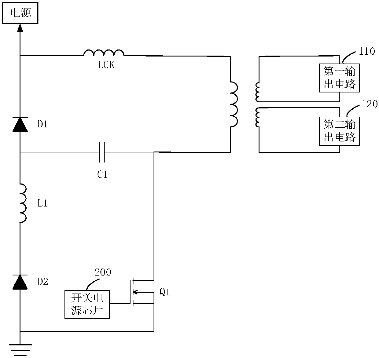
[0022] see figure 1 , a flyback power supply circuit, comprising: a first diode D1, a second diode D2, a primary inductor L1, a first capacitor C2, a switch tube Q1, a transformer T1 and an output circuit 100, the primary side of the transformer T1 One end of the winding is connected to the cathode of the first diode D1, and is used to connect to the power supply, and the other end of the primary winding of the transformer T1 is connected...


PUM


Abstract

The invention relates to a flyback power supply circuit. One end of a primary winding of a transformer is connected with a cathode of a first diode and used for being connected with a power supply, the other end of the primary winding of the transformer is connected with one end of a first capacitor and the input end of a switch tube, the other end of the first capacitor is connected with an anodeof the first diode, the anode of the first diode is connected with one end of a primary inductor, the other end of the primary inductor is connected with a cathode of a second diode, an anode of thesecond diode is connected with the output end of the switch tube, and the output end of the switch tube is grounded. voltage clamps at both ends of the switch tube can be located at a maximum withstanding voltage of the switch tube when the switch tube is switched on to off, when the switch tube is switched on again, the voltage clamps at both ends of the switch tube can be located at an input voltage, the condition that breakdown of the switch tube caused by transformer leakage inductance is effectively avoided, and compared with traditional flyback power supply circuits, the advantage of high working reliability is achieved.

Description

technical field [0001] The present application relates to the technical field of control circuits, in particular to a flyback power supply circuit. Background technique [0002] The flyback power supply is the flyback transformer switching power supply. When the primary coil of the transformer is excited by the DC pulse voltage, the secondary coil of the transformer does not provide power output to the load, but only when the excitation voltage of the primary coil of the transformer is turned off. A circuit that provides power output to the load after it is disconnected. It has the advantages of low cost, simple control, and small circuit size, and is widely used in controller circuits of home appliances, such as controllers of home appliances such as air conditioners. [0003] However, the transformer of the flyback power supply has a large leakage inductance, especially at the moment when the switch tube of the flyback power supply is turned on to off, it will cause a lar...

Claims


Application Information

Patent Timeline
IPC IPC(8): H02M3/335
Inventor 金国义黄银彬史欧阳郑嘉良刘梦坷颜培炎
Owner GREE ELECTRIC APPLIANCES INC
Learn More