Flow forming machine and forming method for producing a wheel

A molding method and molding machine technology, applied in the direction of rims, transportation and packaging, vehicle parts, etc., can solve the problems of high cost, time-consuming and cost, and achieve the effect of increasing the diversity of shapes

Active Publication Date: 2019-04-26
LEIFELD METAL SPINNING AG
View PDF9 Cites 0 Cited by
  • Summary
  • Abstract
  • Description
  • Claims
  • Application Information

AI Technical Summary

Problems solved by technology

However, the process is time consuming and therefore costly

Method used


Image

  • Flow forming machine and forming method for producing a wheel
  • Flow forming machine and forming method for producing a wheel
  • Flow forming machine and forming method for producing a wheel

Examples


Embodiment Construction

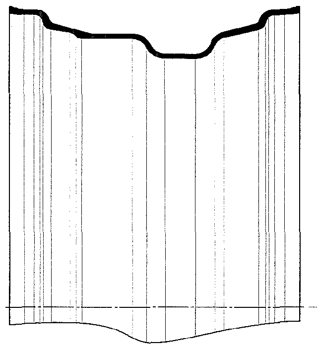
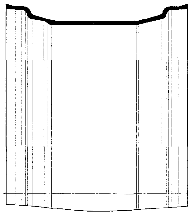
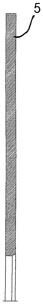
[0036] The spin forming machine 10 according to the invention has a spinning mandrel 20 and an opposite counter mandrel 12, between which the workpiece 5 is axially clamped by means of a disc-shaped hub region 6 with a central fixed Core hole and surrounding area to be formed 7. The mating mandrel 12 and the spinning mandrel 20 are rotatably mounted on drive flanges 16 and 17, respectively, and are connected to one, preferably each, not shown rotary drives, wherein the vertical shafts can be rotated during the forming process. The straight central axis of rotation 2 drives in rotation the spinning mandrel 20 , the counter mandrel 12 and the clamped workpiece 5 .

[0037] The spinning mandrel 20 has a central base support 22 at the free end of which an annular or disk-shaped front element 24 is releasably fastened by means of bolts. As with the opposite mating mandrel 12 (provided with the profiled surface 14 ), the front element 24 is adapted to the shape of the workpiece 5 t...


PUM


Abstract

The invention relates to a flow forming machine and a forming method for producing a wheel (50) with a rim (60) from a workpiece (5), comprising a pressure mandrel (20), the exterior of which is designed to form the rim (60); a mating mandrel (12), wherein the workpiece (5) is clamped against the pressure mandrel (20) or the mating mandrel (12); a rotational drive; and at least one pressure roller(40) which can be advanced towards the workpiece (5) in order to form the rim (60). According to the invention, the pressure mandrel (20) has a sleeve-shaped circumferential element (30) which can bemoved axially during the forming process, and the pressure mandrel (20) has a main support (22) on which the circumferential element (30) is mounted in an axially movable manner. A front element (24)is arranged on a free front face of the main support (22), and a radial hub (52) or a drop center (64) can be axially clamped between the front element (24) of the pressure mandrel (20) and the mating mandrel (12). A controller is provided by means of which the at least one pressure roller (40) and the circumferential element (30) of the pressure mandrel (20) can be moved axially in a matching manner relative to the workpiece (5) while forming the rim (60).

Description

technical field [0001] The invention relates to a spinning machine for the manufacture of wheels, in particular wheels, having a rim formed from a workpiece. According to the preamble of claim 1, the spinning machine has a spinning mandrel, the outer side of which is constructed For forming wheel rims; mating mandrel, which can be moved axially relative to the spinning mandrel, where the workpiece is axially clamped on the spinning mandrel and / or mating mandrel; rotary drive, which is used to rotate A spinning mandrel and a mating mandrel with a clamped workpiece are driven in a stable manner; and at least one pressure roller can be fed axially and radially to the workpiece for forming the rim. [0002] The invention also relates to a forming method for the manufacture of a wheel, in particular a wheel with a rim formed from a workpiece, wherein according to the preamble of claim 8: the workpiece is clamped on a spinning mandrel and / or a mating core On the shaft, the outer si...

Claims


Application Information

Patent Timeline
Patent Type & Authority Applications(China)
IPC IPC(8): B21D22/16B21D53/30
CPCB21D22/16B21D53/30
Inventor B.尼利斯
Owner LEIFELD METAL SPINNING AG
Why Eureka
Try Eureka