Pressurization type steam-aging device

A technology of aging device and pressurized steam, which is applied in the field of lime calcination to reduce the frequency of equipment maintenance and improve the aging efficiency

Active Publication Date: 2019-04-26
NIPPON STEEL CORP
View PDF6 Cites 0 Cited by
  • Summary
  • Abstract
  • Description
  • Claims
  • Application Information

AI Technical Summary

Problems solved by technology

[0016] However, even with the aging method of Patent Document 4, a reduction

Method used


Image

  • Pressurization type steam-aging device
  • Pressurization type steam-aging device
  • Pressurization type steam-aging device

Examples


Example Embodiment

[0065] The inventors have conducted intensive research on suppressing the frequency of equipment maintenance and improving the aging efficiency in the pressurized steam aging device. As a result, the following findings were obtained.

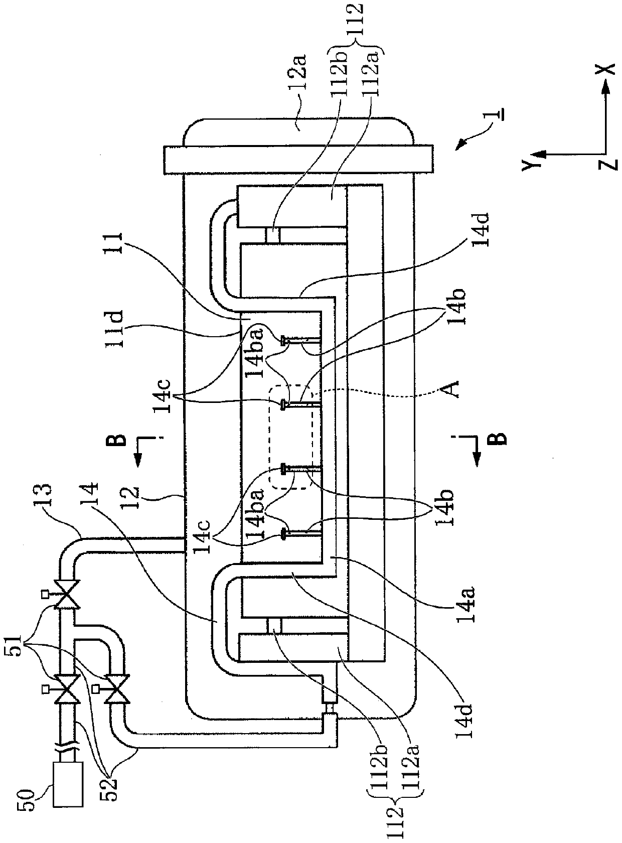
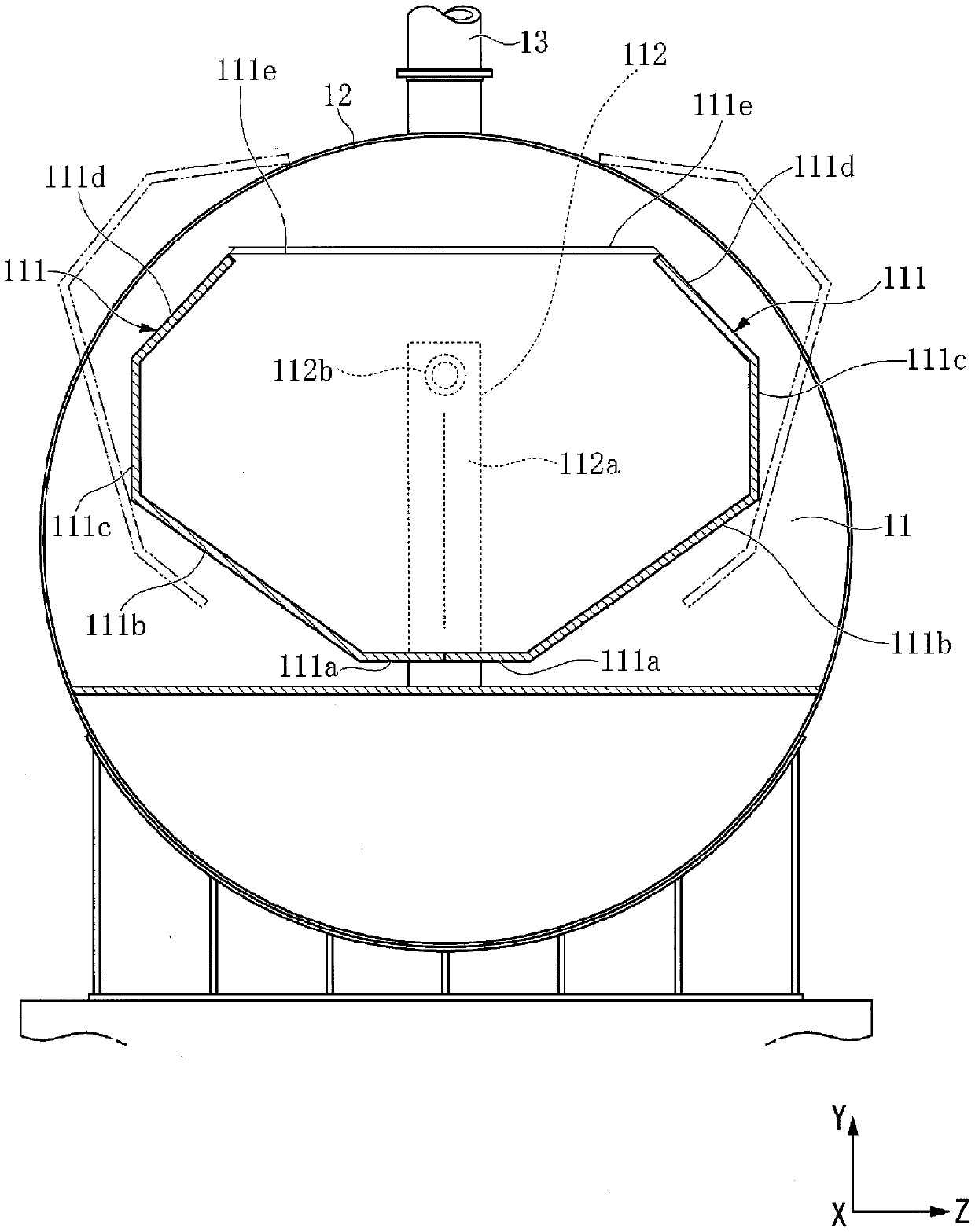
[0066] Such as Figure 10A , Figure 10B As in the illustrated prior art, when the hole 205a for ejecting steam is formed in the pipe 205 arranged in the longitudinal direction, the steelmaking slag in the vicinity of the hole 205a exists with a high degree of filling. In this case, steam is prevented from being ejected from the hole 205a. In addition, there is a risk of clogging of the hole 205a. Therefore, if the steam hole is formed on the side surface of the branch pipe portion that rises in the vertical direction, the steelmaking slag dropped from above and charged collides with the upper part of the pipe, and the filling degree of the steelmaking slag near the hole can be reduced. As a result, steam can be effectively ejected from the holes...


PUM

PropertyMeasurementUnit
Lengthaaaaaaaaaa
Diameteraaaaaaaaaa

Abstract

A pressurization type steam-aging device for performing pressurization type steam-aging on steel slag by using pressurized steam is provided. The device includes a slag accommodation vessel, a pressure vessel, first piping, and second piping. The second piping comprises a main pipe part and a branch pipe part having jet orifices formed in the side surface thereof. Taking H (mm) to be the dimensionin the height direction of an accommodation region of the slag accommodation vessel, the jet orifices are disposed in a height direction region of 0.3*H to 0.6*H in the accommodation region.

Description

technical field [0001] The present invention relates to a pressurized steam aging device for aging steelmaking slag containing unresidue lime (also called free lime) discharged from a converter, an electric furnace, etc., using pressurized steam for a short time. [0002] This application claims priority based on Patent Application No. 2017-011870 for which it applied in Japan on January 26, 2017, and uses the content here. Background technique [0003] The steelmaking slag produced in the steelmaking process is hard and its surface has an angular shape, so it fits well during road rolling and has excellent properties as a roadbed material. [0004] However, in the steelmaking slag, a part of quicklime used as a dephosphorization agent and a desulfurization agent is not completely combined with other molecules, and remains in the state of unsludged lime. [0005] Therefore, when the steelmaking slag is used as it is as a roadbed material, hydration reaction occurs over time...

Claims


Application Information

Patent Timeline
IPC IPC(8): C04B5/00C21C5/28F27D15/00
CPCC04B5/00C21C5/28F27D15/00
Inventor 浜崎拓司神保正人森下茂
Owner NIPPON STEEL CORP
Why Eureka
Try Eureka