Excavator
A technology for excavators and boom cylinders is applied in the field of excavators to achieve the effect of suppressing warping
- Summary
- Abstract
- Description
- Claims
- Application Information
AI Technical Summary
Problems solved by technology
Method used
Image
Examples
Deformed example 1
[0111] By performing the correction of the operation of the attachment 12 at high speed, it is theoretically possible to prevent the operator from being aware of the correction and to suppress the warping. However, if the response delay increases, the operator may feel a discrepancy between his own operation and the operation of the attachment 12 . Therefore, the shovel 1 may issue a notification or an alarm to the operator that the shovel has occurred together with the correction of the operation of the attachment 12 . The notification and alarm may utilize an auditory mechanism that emits a voice message or a warning sound, or may utilize a visual mechanism such as a display or a warning light, or may utilize a tactile (physical) mechanism that generates vibration or the like.
[0112] Thereby, the operator can recognize that a deviation between the operation and the motion is caused by the automatic correction of the motion of the attachment 12 . And, when the notification...
Deformed example 2
[0114] Sometimes the operator also intentionally wants to take advantage of the tilt of the vehicle body. Therefore, what is necessary is just to enable an operator to turn off and on the lifting suppression function. Figure 10 It is a figure which shows an example of the display 700 and the operation part 710 provided in the cab of a shovel. For example, on the display 700 , a dialog 702 and an icon are displayed to ask the operator to turn on / off (enable / disable) the tilting suppression function. The operator uses the operation unit 710 to select whether to enable or disable the warping correction function. The operation unit 710 may be a touch panel, and the operator can designate valid / invalid by touching an appropriate part on the display.
[0115] Figure 11 (a), Figure 11 (b) is a figure explaining the situation which should invalidate a warpage suppression function. Figure 11 (a) is a case where the traveling body 2 falls deeply and tries to escape from the pla...
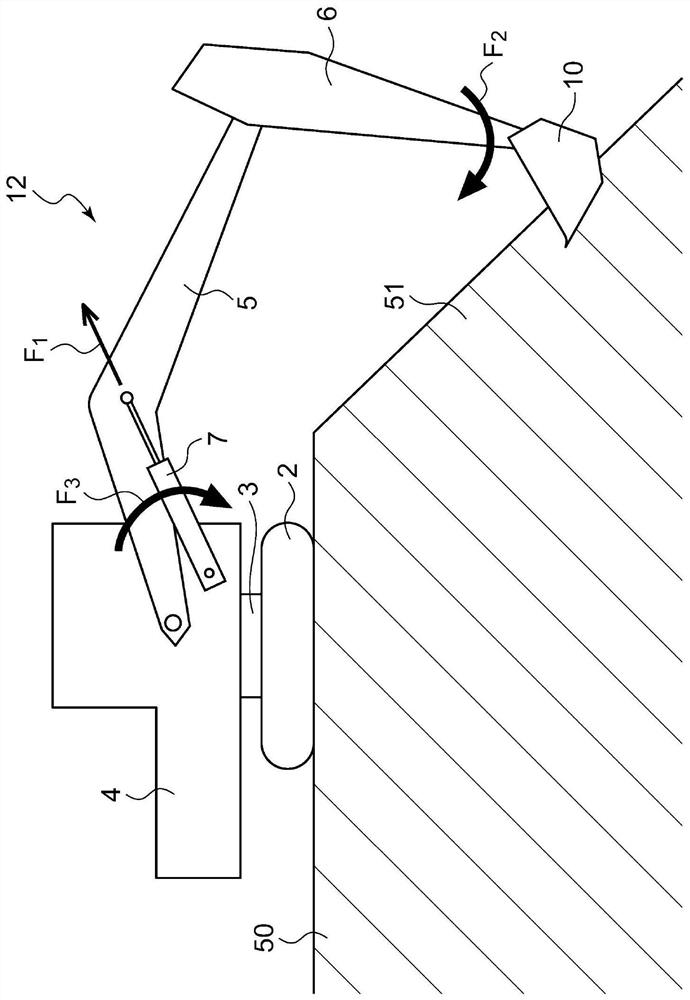
Deformed example 3
[0118] refer to figure 2 , the tilting caused by the operation of the boom has been described, but the application of the present invention is not limited thereto. Figure 12 (a), Figure 12 (b) is a figure explaining another example of back warping. Figure 12 (a) shows a state in which the bucket 10 is in contact with the hard rock 800 when the bucket 10 is operated to scrape sand and earth into the bucket. In this case, the rear is intended to be tilted with the front as a fulcrum.
[0119] Figure 12 (b) represents the finishing operation of the slope. In this work, the operation of moving the bucket 10 along the slope is performed, and the boom and the arm are simultaneously operated. At this time, if the bucket 10 collides with the stone 800 embedded in the slope, the rear will be tilted with the front as a fulcrum. even in such Figure 12 (a), Figure 12 (b) Even in such a situation, the above-mentioned lifting suppression function works effectively.
PUM
 Abstract
Description
Claims
Application Information
 - R&D
- Intellectual Property
- Life Sciences
- Materials
- Tech Scout
- Unparalleled Data Quality
- Higher Quality Content
- 60% Fewer Hallucinations
Browse by: Latest US Patents, China's latest patents, Technical Efficacy Thesaurus, Application Domain, Technology Topic, Popular Technical Reports.
© 2025 PatSnap. All rights reserved.Legal|Privacy policy|Modern Slavery Act Transparency Statement|Sitemap|About US| Contact US: help@patsnap.com


