Transition tank

A technology of tank body and filter screen, applied in the field of transition tanks, can solve the problems of low gas phase purity and mixed gas phase, etc., and achieve the effect of promoting condensation and collection, ensuring purity, and improving purity.

Active Publication Date: 2019-04-30
NINGBO BEILUN LEIAO AUTOMATION EQUIP
View PDF8 Cites 0 Cited by
  • Summary
  • Abstract
  • Description
  • Claims
  • Application Information

AI Technical Summary

Problems solved by technology

[0004] In order to solve the problem that the transition tank in the prior art usually only simply separates the gas-liquid mixed phase through the condenser tube, such a separation operation makes the purity of the gas phase not high and the liquid phase is not properly treated in time after being separated and collected, which makes it easy to volatilize and mix in again. The problem of the gas phase, the present invention provides a transition tank that can efficiently realize gas-liquid separation

Method used


Image

  • Transition tank
  • Transition tank
  • Transition tank

Examples


Embodiment 1

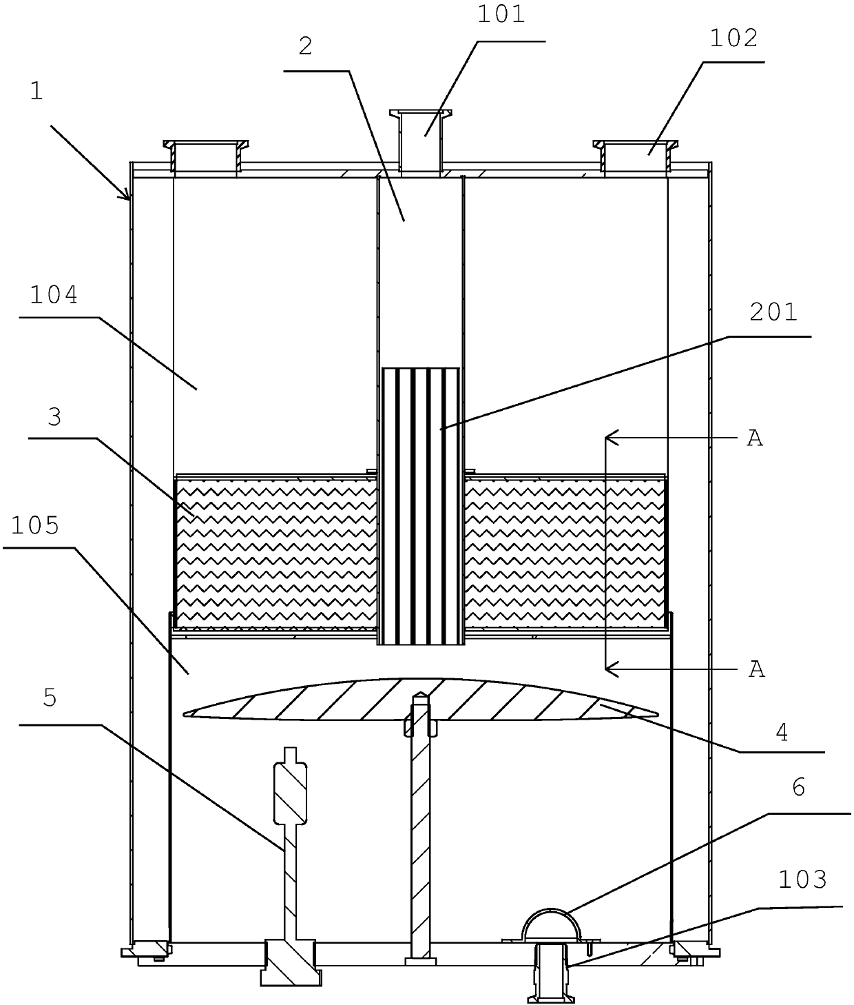
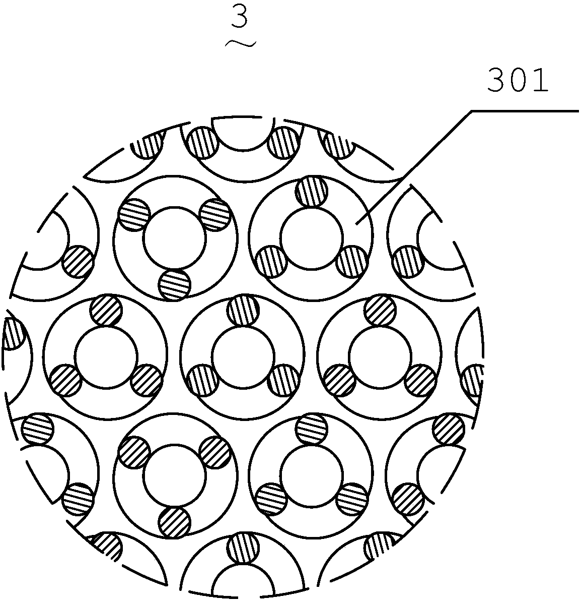
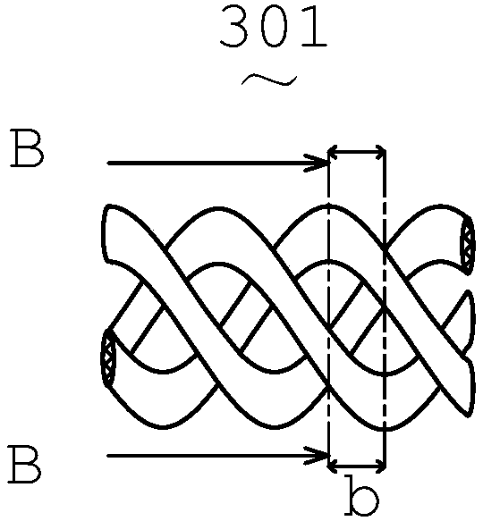
[0045] like figure 1 A transition tank shown includes a tank body 1, an air inlet 101, an air outlet 102, and a liquid discharge port 103. The air inlet 101 and the air outlet 102 are arranged on the top of the tank body 1, and the liquid outlet 103 is arranged on the top of the tank body. 1 bottom end, the tank body 1 is provided with an air intake passage 2, the upper end of the air intake passage 2 is sealed with the air inlet 101, the inner cavity of the lower half of the air intake passage 2 is provided with a condensation pipe 201, and the outside of the air intake passage 2 is sleeved with The filter screen 3 is provided with a return cover plate 4 under the air intake channel 2, and a liquid level sensor 5 is provided on the bottom surface of the inner cavity of the tank body 1.

[0046] The tank body 1 of the transition tank is divided into the upper cavity 104 and the lower cavity 105 with the filter screen 3 as the boundary, and the gas enters the tank body 1 of the...

Embodiment 2

[0048] like figure 1 , figure 2 , image 3 and Figure 4 A transition tank shown includes a tank body 1, an air inlet 101, an air outlet 102, and a liquid discharge port 103. The air inlet 101 and the air outlet 102 are arranged on the top of the tank body 1, and the liquid outlet 103 is arranged on the top of the tank body. 1 bottom end, the tank body 1 is provided with an air intake passage 2, the upper end of the air intake passage 2 is sealed and connected with the air inlet 101, the inner cavity of the lower half of the air intake passage 2 is provided with a condensation pipe 201, and the outside of the air intake passage 2 is provided with The filter screen 3 is provided with a return cover plate 4 under the air intake channel 2, and a liquid level sensor 5 is provided on the bottom surface of the inner cavity of the tank body 1.

[0049]The tank body 1 of the transition tank is divided into the upper cavity 104 and the lower cavity 105 with the filter screen 3 as t...

Embodiment 3

[0051] like figure 2 , image 3 , Figure 4 , Figure 5 and Image 6 A transition tank shown includes a tank body 1, an air inlet 101, an air outlet 102, and a liquid discharge port 103. The air inlet 101 and the air outlet 102 are arranged on the top of the tank body 1, and the liquid outlet 103 is arranged on the top of the tank body. 1 bottom end, the tank body 1 is provided with an air intake passage 2, the upper end of the air intake passage 2 is sealed with the air inlet 101, the inner cavity of the lower half of the air intake passage 2 is provided with a condensation pipe 201, and the outside of the air intake passage 2 is sleeved with A filter screen 3, a return cover 4 is provided under the air intake channel 2, a liquid level sensor 5 is provided on the bottom surface of the inner cavity of the tank body 1, a buffer mechanism 7 is provided in the inner cavity of the tank body 1, and the buffer mechanism 7 is provided with an upper opening and a side opening , t...


PUM

PropertyMeasurementUnit
densityaaaaaaaaaa

Abstract

The invention relates to a transition tank which comprises a tank body, an air inlet, an air outlet and a liquid outlet, the gas inlet and the gas outlet are formed in the top end of the tank body, the liquid outlet is formed in the bottom end of the tank body, an air inlet channel is formed in the tank body, the upper end of the air inlet channel is hermetically connected with the air inlet, theinner cavity of the lower half part of the air inlet channel is provided with a condensation pipe, a filter screen is arranged outside the air inlet channel in a sleeved mode, a backflow cover plate is arranged below the air inlet channel, a liquid level sensor is arranged on the bottom surface of the inner cavity of the tank body, the two-phase separation of gas and liquid two phases in a gas isrealized by arranging the condensation pipe and the filter screen structure, and the separation degree is high, so that the purity of a separated and filtered gas phase is extremely high.

Description

technical field [0001] The invention relates to a transition tank, in particular to a transition tank capable of efficiently realizing gas-liquid separation. Background technique [0002] Gas-liquid separation is a step that needs to be realized in many jobs. For example, when it is necessary to realize the compression of gas in a gas compressor, if the gas contains small liquid particles or some condensable gas components, the compressed gas During the process, due to the increase of gas pressure, small liquid particles aggregate into larger liquid or condensable gas components condense into liquid, so that the compressed gas is mixed with liquid impurities, which reduces the quality of the compressed gas and may cause damage to the gas. The compressor is damaged, and the existing transition tank usually only simply separates the gas-liquid mixed phase through the condensation tube. Such separation operation makes the purity of the gas phase not high and the liquid phase is...

Claims


Application Information

Patent Timeline
Patent Type & Authority Applications(China)
IPC IPC(8): B01D53/00B01D50/00B01D46/00B01D53/04B01D53/26B01D5/00
CPCB01D5/00B01D5/0027B01D46/00B01D46/0036B01D50/00B01D53/002B01D53/04B01D53/261
Inventor 刘际波单荣昌
Owner NINGBO BEILUN LEIAO AUTOMATION EQUIP
Why Eureka
Try Eureka