Eureka AIR delivers breakthrough ideas for toughest innovation challenges, trusted by R&D personnel around the world.

Inductive automatic wire-replacing system for multi-head wire drawing machine

A multi-head wire drawing machine and automatic wire changing technology, applied in the field of multi-head wire drawing production, can solve the problems of knotting, waste of personnel efficiency, high frequency of material change, reduce wire breakage, improve wire change efficiency, and ensure stability. Effect

Active Publication Date: 2019-04-30
铜陵顶科镀锡铜线有限公司
View PDF11 Cites 0 Cited by
  • Summary
  • Abstract
  • Description
  • Claims
  • Application Information

AI Technical Summary

Problems solved by technology

If the new material cannot be moved to the pay-off guide wheel assembly in time, due to the excessive bevel angle of the pay-off, it will cause the phenomenon of scraping and knotting of the pay-off line, and then cause the breakage
Obviously, the above-mentioned traditional refueling method will cause a great waste of personnel efficiency. At the same time, due to the large amount of wire required by the multi-head wire drawing system, the frequency of refueling is extremely high. Cause disconnection phenomenon, which brings many troubles to the actual wire drawing production

Method used


Image

  • Inductive automatic wire-replacing system for multi-head wire drawing machine
  • Inductive automatic wire-replacing system for multi-head wire drawing machine
  • Inductive automatic wire-replacing system for multi-head wire drawing machine

Examples


Embodiment Construction

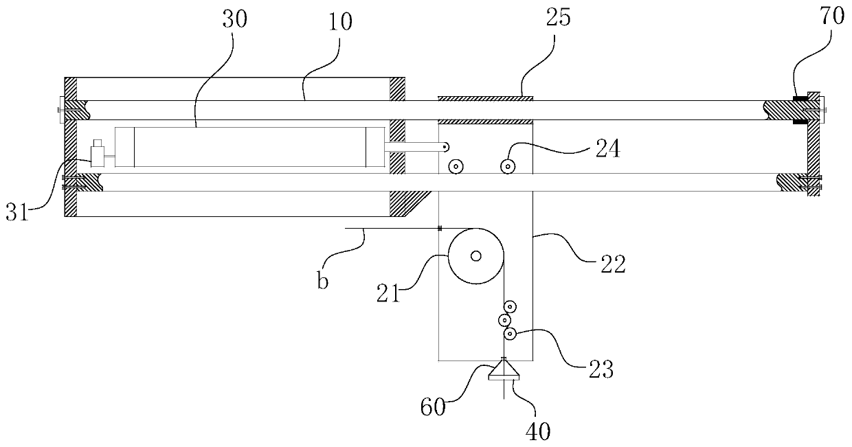
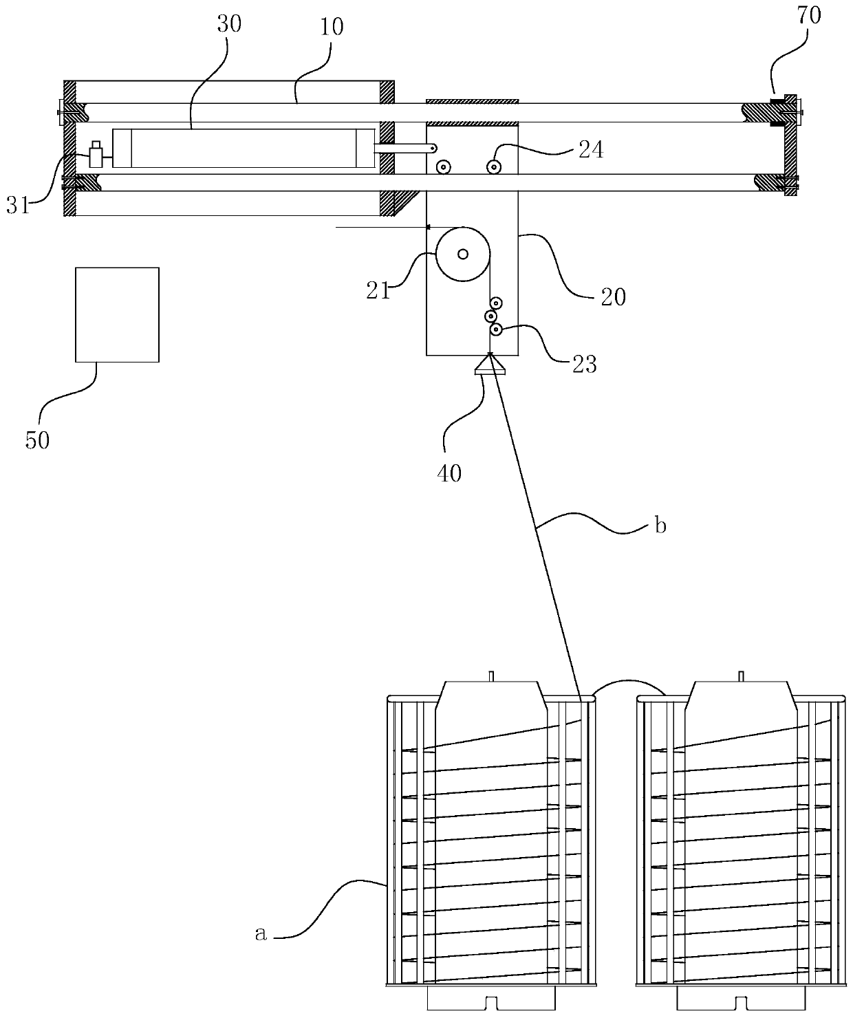
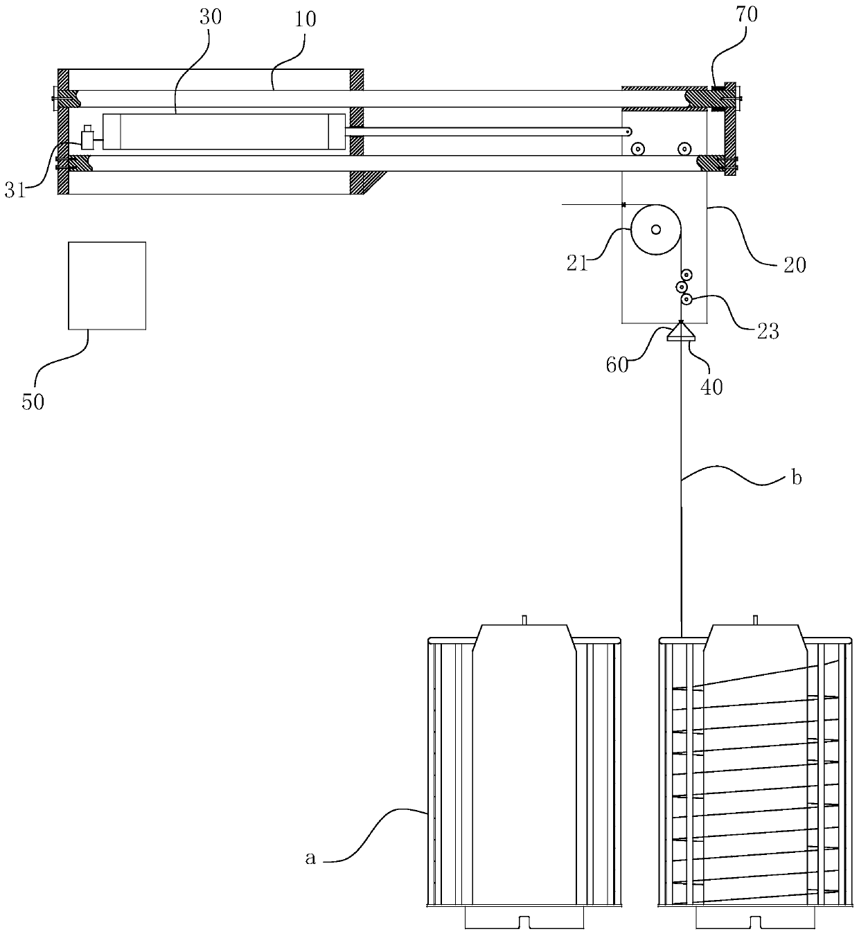
[0027] For ease of understanding, combined here Figure 1-3 , the concrete structure and working mode of the present invention are further described as follows:

[0028] The specific structure of the present invention is as Figure 1-3 As shown, its main structure includes a pay-off basket a and a mobile pay-off assembly located directly above the pay-off basket a, and the mobile pay-off assembly is then fixed on the pay-off bracket. in:

[0029] by figure 1 As an example, the mobile pay-off assembly includes a horizontal guide rail 10 , a cylinder that is a driving part 30 , a mobile boom 20 and a buffer pad 70 . And for the mobile boom 20, it is used as a carrier on the one hand, so that the reversing wheel 21, the stress wheel 23, the moving roller 24 and even the guide sleeve 25 are arranged conveniently; The purpose of reciprocating sliding relative to the horizontal guide rail 10 is achieved by relying on the cooperation of the guide sleeve 25 and the moving roller 2...


PUM


Abstract

The invention belongs to the technical field of multi-head wire drawing production and particularly relates to an inductive automatic wire-replacing system for a multi-head wire drawing machine. The inductive automatic wire-replacing system comprises pay-off baskets and a movable pay-off assembly, the movable pay-off assembly comprises a horizontal guide rail fixed to a pay-off bracket, and the guiding direction of the horizontal guide rail is parallel to the arranging direction of the two sets of pay-off baskets below the horizontal guide rail; a movable lifting arm is placed on the horizontal guide rail, wherein the movable lifting arm and the horizontal guide rail constitute sliding block and guide rail fit, and a direct-changing wheel used for changing the traveling direction of wire bodies at the pay-off baskets is arranged on the movable lifting arm; and the inductive automatic wire-replacing system further comprises a driving part used for pushing the movable lifting arm to enable the movable lifting arm to slide relative to the horizontal guide rail, and an annular contact-type sensor fixed to a wire body traveling path between the direction changing wheel and the pay-off baskets. According to the inductive automatic wire-replacing system, the knotting wire-breaking situation caused by the fact that material moving is not in time can be effectively avoided, the wire-replacing efficiency of wire drawing operation is greatly improved, and the line body breaking phenomenon can be lowered accordingly.

Description

technical field [0001] The invention belongs to the technical field of multi-head wire drawing production, and in particular relates to an induction-type automatic wire changing system for a multi-head wire drawing machine. Background technique [0002] The wire drawing machine is mainly used for the production and processing of metal wire products. Through the wire drawing process, the diameter, roundness, internal metallographic structure, surface finish and even straightening of the wire can meet the specified standards. The pay-off system is the source of the production line's work, and it is also one of the most important components of the wire drawing production line. The pay-off system usually adopts basket-type pay-off, that is, firstly fix the pay-off guide wheel assembly directly above the wire basket, and then pass the wire body in the wire basket through the pay-off guide wheel assembly and enter the wire drawing machine. However, in the actual production proces...

Claims


Application Information

Patent Timeline
IPC IPC(8): B21C47/24B21C1/02
CPCB21C1/02B21C47/24
Inventor 陈彬陈鼎彪陈城曹永成黄亮汪洋孙玉好胡伯顺吴晓山张槐林吴智云黄爱军李齐靖秦磊王帮助凌小八查敏王建华
Owner 铜陵顶科镀锡铜线有限公司
Why Eureka
Eureka Blog
Learn More