

A ratchet wrench
A technology of ratchet wrench and ratchet wheel, which is applied in the field of ratchet wrench, and can solve the problems of losing the fulcrum, slipping and breaking of the ratchet wheel 3, etc.
- Summary
- Abstract
- Description
- Claims
- Application Information
AI Technical Summary
Problems solved by technology
Method used
Image

Examples
Embodiment Construction
[0057] In order to describe in detail the structural features and effects of the present invention, preferred embodiments are listed hereafter in conjunction with the drawings.
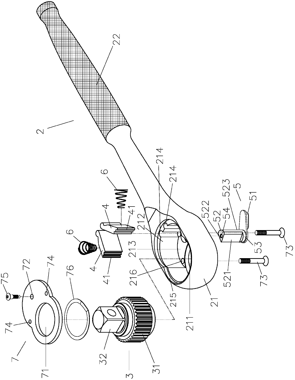
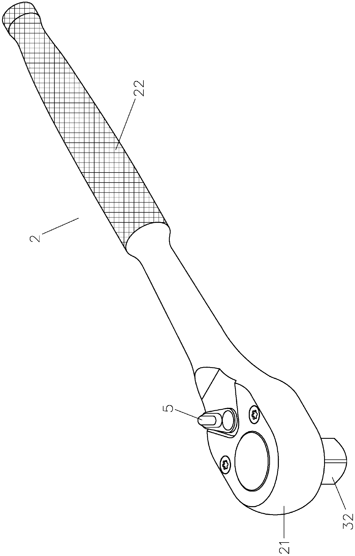
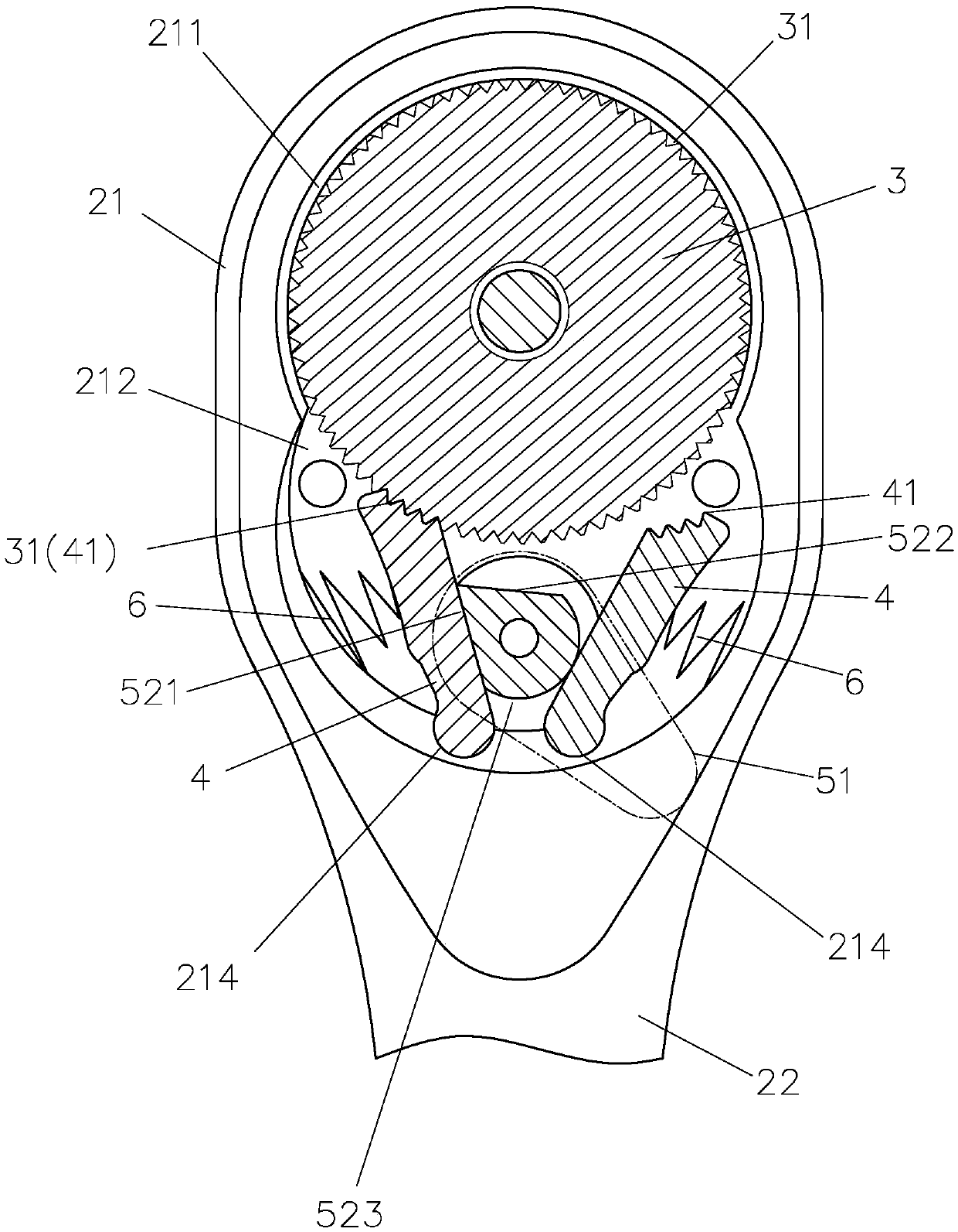
[0058] See Figure 6 to Figure 10 Shown is the first embodiment of the ratchet wrench of the present invention, which includes: a body 20, a ratchet 30, two detent blocks 40, a reversing member 50, two elastic members 60 and a cover 70; among them,
[0059] The body 20 has a head 201 and a handle 202. The head 201 extends from one end of the handle 202. The head 201 has a first accommodating groove 2011 and a communicating second accommodating groove 2012. The accommodating groove 2011 and the second accommodating groove 2012 are open on both sides of the head 201, and the first accommodating groove 2011 and the second accommodating groove 2012 have a connecting portion 2013 on one side of the head 201, and the second accommodating groove The wall surface of the groove 2012 different from the first receivi...
PUM
 Abstract
Description
Claims
Application Information