A deep well type natural pressure intake and drainage structure

An inflow and drainage, deep well technology, applied in the field of aquaculture, can solve problems such as the inability to filter the drainage outlet and the lack of intelligent monitoring equipment, and achieve the effects of improving cleanliness, improving controllability, and preventing clogging

Active Publication Date: 2021-05-04
湛江市鸿振机械设备有限公司
View PDF4 Cites 0 Cited by
  • Summary
  • Abstract
  • Description
  • Claims
  • Application Information

AI Technical Summary

Problems solved by technology

[0005] The purpose of the present invention is to provide a deep well type natural pressure inlet and drainage structure in order to solve the problems that the outlet of the water inlet cannot be filtered, there is no monitoring equipment and the intelligence is low.

Method used


Image

  • A deep well type natural pressure intake and drainage structure
  • A deep well type natural pressure intake and drainage structure
  • A deep well type natural pressure intake and drainage structure

Examples


Embodiment 1

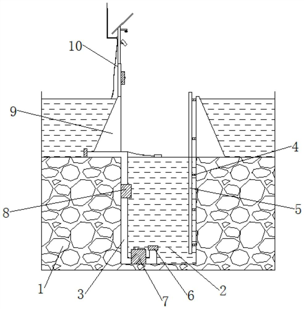
[0033] Embodiment one, with reference to Figure 1-6 , the present invention provides a technical solution: a deep well type natural pressure inlet and drainage structure, including a ground 1, an inlet and drain pipe 3, a control valve 7 and a monitoring device 10, the middle part of the ground 1 is fixedly connected with a deep well 2, and a deep well 2 One side of the inner side is embedded with an inlet and outlet pipe 3, and the other side of the inner side of the deep well 2 is embedded with a connecting rod 4. The top of one side of the inlet and outlet pipe 3 is movably connected with a water inlet head 6, and the other side of the inlet and outlet pipe 3 runs through A control valve 7 is connected, the middle part of the inlet and outlet pipes 3 is connected with a fixing device 8 , the top of the inlet and outlet pipes 3 is connected with a water retaining wall 9 , and the top of the water retaining wall 9 is embedded with a monitoring device 10 ;

[0034] The surfac...

Embodiment 2

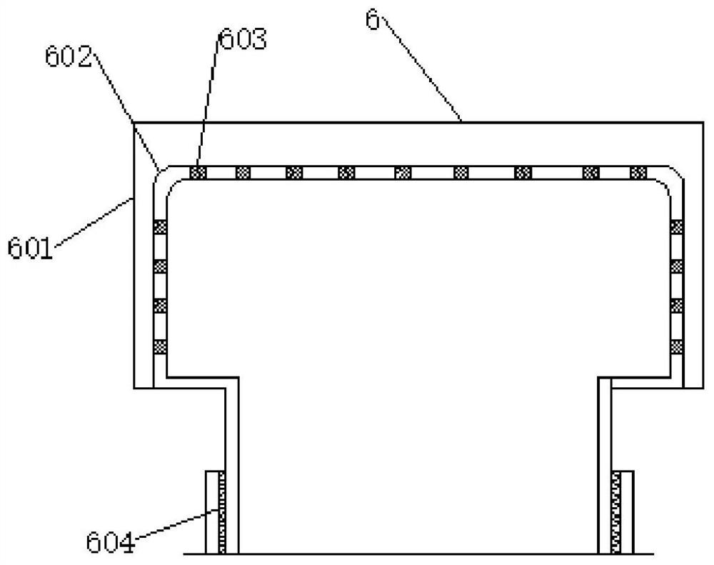
[0044] Embodiment two, refer to figure 2 , the water inlet head 6 is composed of a filter screen 601 on the surface of the water inlet head 6, a filter plate 602 at the top of the water inlet head 6, a filter hole 603 on the surface of the filter plate 602, and a fixed thread 604 at the bottom of the water inlet head 6, and There are two water inlet heads 6, and the water inlet head 6 is installed at both ends of the inlet and outlet pipes 3. When the device is in use, the filter screen 601 can prevent impurities from entering the inlet and outlet pipes, thereby preventing the inlet and outlet pipes 3 from being blocked. The filter hole 603 on the surface of 602 can further filter the impurities in the water, thereby improving the cleanliness of the water, and then making the device operate normally. Being clogged increases the usability of the device.

Embodiment 3

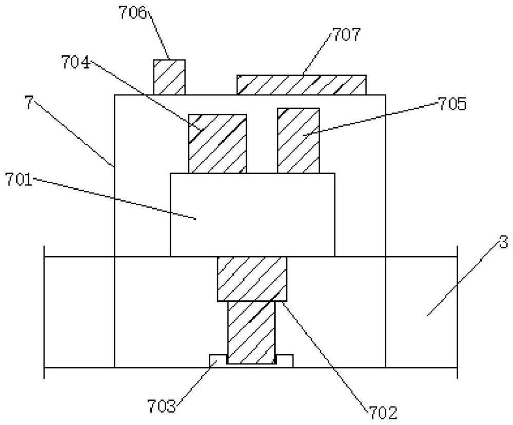
[0045] Embodiment three, refer to image 3 The control valve 7 is composed of a hydraulic device 701 in the middle of the control valve 7, a telescopic post 702 at the bottom of the hydraulic device 701, a groove 703 at the bottom of the telescopic post 702, a controller 704 on one side of the top of the hydraulic device 701, and another at the top of the hydraulic device 701. The signal transceiver 705 on one side and the temperature sensor 706 on the top side of the control valve 7 are jointly composed. When the natural tide or water body on the ground at the well rises, the water body will generate pressure, so that the controller 704 controls the hydraulic device 701 to open the channel , and then flow out from the connected water pipe on the ground to the outlet of the pipe at the bottom of the well, the water body in the well will gradually increase with the pressure of the external water body, and vice versa, the water body in the well will also decrease with the decreas...


PUM


Abstract

The invention discloses a deep well type natural pressure inlet and drainage structure. In the invention, it includes ground, inlet and outlet pipes, control valves and monitoring devices. The middle part of the ground is fixedly connected with a deep well, and the inner side of the deep well is embedded and connected with an inlet and drain The other side of the inner side of the deep well is embedded with a connecting rod, the top of one side of the inlet and outlet pipe is movably connected with a water inlet head, and the fixing screw is connected with a fixing plate. The fixing plate helps to fix the inlet and outlet pipes, improving the water inlet and drainage The stability of the tube, the telescopic rod can change the height of the camera, the battery box can store electric energy and provide electric energy for the device, the camera can monitor the deep well constantly, the LED light can provide the light source for the operator, and the photovoltaic solar panel can convert light energy into Electric energy, the monitoring device helps to monitor the deep well constantly, thereby improving the intelligence of the device, the control valve helps to control the entry or discharge of water, and improves the controllability of the inlet and outlet pipes, which has broad development prospects in the future .

Description

technical field [0001] The invention relates to the technical field of breeding, in particular to a deep well type natural pressure inlet and drainage structure. Background technique [0002] Marine deep-water aquaculture will be more and more valued by fish farming. The use of marine deep-water aquaculture cages can open up large-scale fish farming production areas in the deep sea, and the deep-sea fish farming environment is much better than the shallow water fish farming environment. On the one hand, the deep-sea fish farming environment The marine environment is less polluted and affected by human activities, and is more suitable for fish farming. On the other hand, the origin of deep-sea marine farming is often far away from the mainland, and can even be established in the environment of the high seas. The natural condition factors of tide, soft current and wind direction can be fully utilized in the process of fish farming. [0003] At present, aquaculture is generall...

Claims


Application Information

Patent Timeline
Patent Type & Authority Patents(China)
IPC IPC(8): A01K63/04
Inventor 邹权明
Owner 湛江市鸿振机械设备有限公司
Why Eureka
Try Eureka