
Self-loading and unloading turnover box

A turnover box, self-loading and unloading technology, applied in the field of transport boxes, can solve the problems of unadjustable height, complicated loading and unloading process, high cost of airbags, etc., and achieve the effect of good practicability, good safety and stability, and simple structure

Pending Publication Date: 2019-05-03
JINAN XINTONG SPECIAL VEHICLE
View PDF9 Cites 3 Cited by
  • Summary
  • Abstract
  • Description
  • Claims
  • Application Information

AI Technical Summary

Problems solved by technology

[0003] Most of the existing turnover boxes are loaded and unloaded through the following methods. One is to use forklifts or aerial cranes to lift and unload them. Forklifts can only load and unload smaller turnover boxes. Aerial cranes are installed at each logistics point. The second is to use the airbag to lift the turnover box. There is an airbag between the turnover box and the chassis. The upper legs are installed at the four corners, the airbag is deflated, and the car is driven out to realize the loading and unloading of the turnover box. However, the loading and unloading process of this method is complicated, and the cost of the airbag is high. After the turnover box is disassembled, the height cannot be adjusted, which is inconvenient to use. Poor practicality

Method used


Image

  • Self-loading and unloading turnover box
  • Self-loading and unloading turnover box
  • Self-loading and unloading turnover box

Examples


Embodiment Construction

[0034] In order to enable those skilled in the art to better understand the technical solutions in the present invention, the technical solutions in the embodiments of the present invention will be clearly and completely described below in conjunction with the drawings in the embodiments of the present invention. Obviously, the described The embodiments are only some of the embodiments of the present invention, not all of them. Based on the embodiments of the present invention, all other embodiments obtained by persons of ordinary skill in the art without making creative efforts shall fall within the protection scope of the present invention.

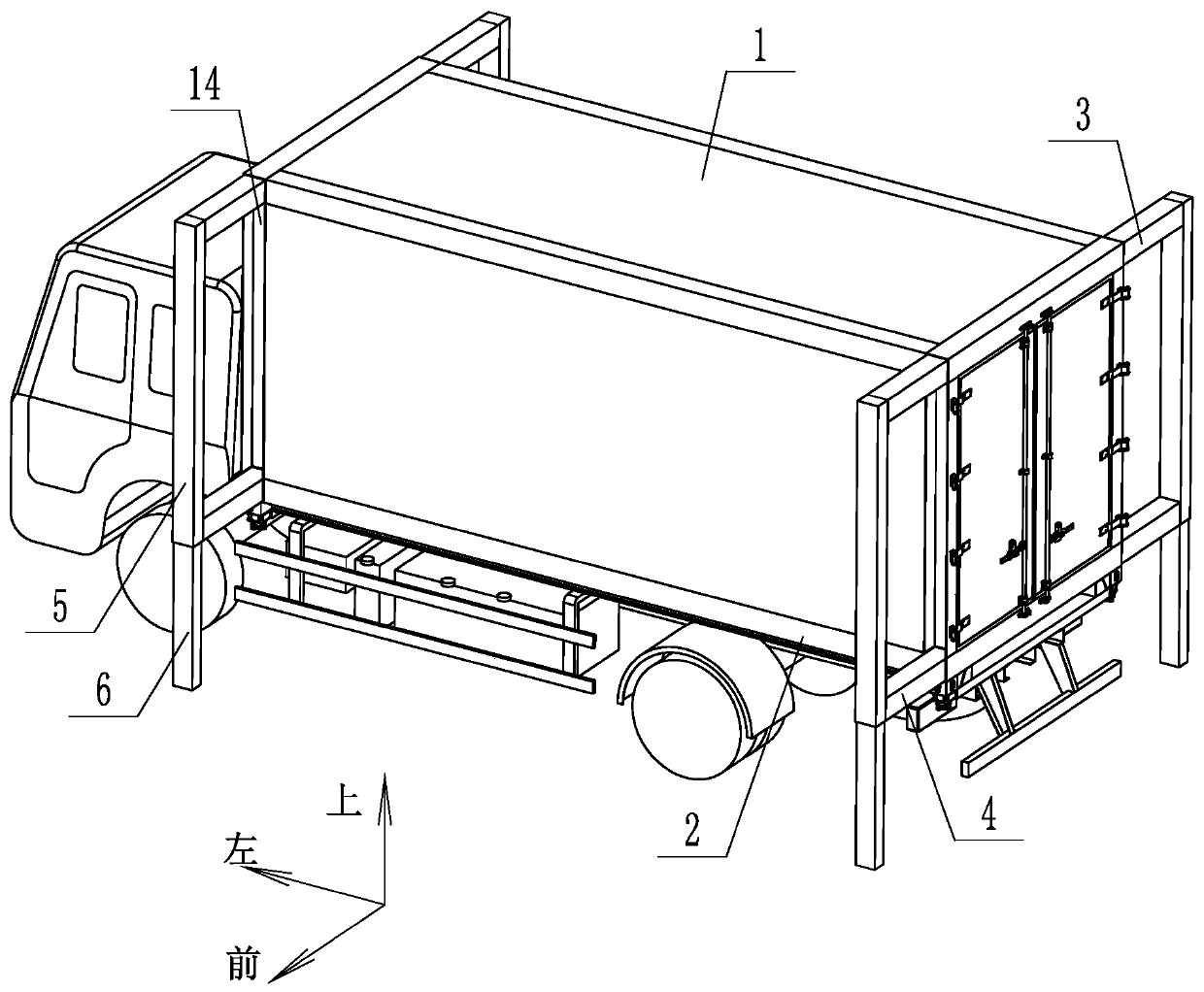
[0035] For the convenience of description, the coordinate system is defined as figure 1 shown.

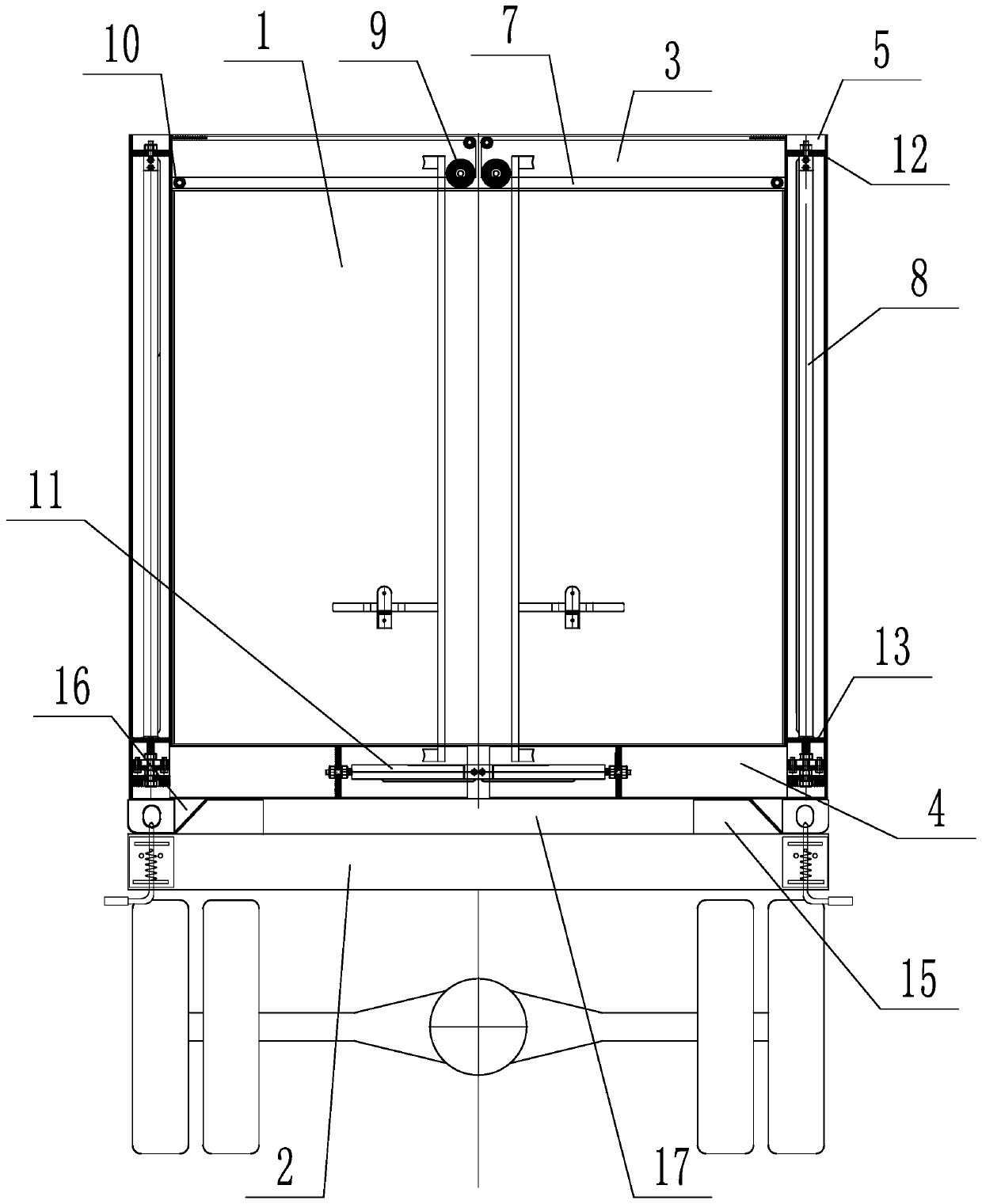
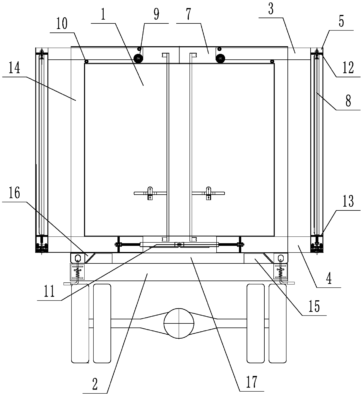
[0036] Such as figure 1 and Figure 4 As shown, a self-loading and unloading turnover box includes a turnover box body 1 and a base 2. The turnover box body 1 is installed on the base 2, and also includes an extended upper arm 3, an exten...


PUM


Abstract

The invention discloses a self-loading and unloading turnover box that comprises a turnover box body and a base, wherein the turnover box body is mounted on the base; the turnover box further comprises an expansion upper support arm, an expansion lower support arm, supporting leg shells and supporting leg guide columns; slideways are arranged at the upper end and the lower end of the turnover boxbody; the upper expansion support arm extends into the upper end slideway; the expansion lower support arm extends into the lower end slideway; a first driving mechanism is arranged between the expansion lower support arm and the lower end slideway; one end of the outer side of the expansion upper support arm and one end of the outer side of the expansion lower support arm are respectively connected with the supporting leg shells; the upper end of the supporting leg guide column extends into the supporting leg shell and is slidably connected with the supporting leg shell, and a second drivingmechanism is arranged between the supporting leg shell and the supporting leg guide column. Self loading and unloading of the turnover box body are achieved, the automation degree is high, the labor intensity is reduced, the structure is simple, and cost is low.

Description

technical field [0001] The invention relates to a transport box, in particular to a self-loading and unloading turnover box. Background technique [0002] Turnover boxes are widely used in the transportation industry, whether it is a special vehicle box, a container, a refrigerator, an electrostatic generator unit power supply box, a garbage turnover box, a military shelter, etc., or a turnover box is used in the postal and logistics industries. [0003] Most of the existing turnover boxes are loaded and unloaded through the following methods. One is to use forklifts or aerial cranes to lift and unload them. Forklifts can only load and unload smaller turnover boxes. Aerial cranes are installed at each logistics point. The second is to use the airbag to lift the turnover box. There is an airbag between the turnover box and the chassis. The upper legs are installed at the four corners, the airbag is deflated, and the car is driven out to realize the loading and unloading of t...

Claims


Application Information

Patent Timeline
Patent Type & Authority Applications(China)
IPC IPC(8): B60P1/64B65D90/00
Inventor 周江周晓鑫
Owner JINAN XINTONG SPECIAL VEHICLE
Learn More