
Manufacturing apparatus of prefabricated rod for optical element blank, and method for manufacturing element blank

A technology for optical components and manufacturing devices, which is applied in the direction of manufacturing tools, glass manufacturing equipment, glass cutting devices, etc., can solve the problems of difficult reduction of manufacturing costs, low material utilization rate, and complicated equipment, so as to improve material utilization rate and save Effects of processing steps and small diameter tolerances

Active Publication Date: 2019-05-03
HUBEI NEW HUAGUANG NEW INFORMATION MATERIALS CO LTD
View PDF5 Cites 3 Cited by
  • Summary
  • Abstract
  • Description
  • Claims
  • Application Information

AI Technical Summary

Problems solved by technology

The molding method has great limitations. Many optical glasses containing rare earth components cannot be pressed once, and must be formed by secondary molding. The secondary molding process is complicated and the equipment is complicated, requiring a large number of operators. , it is difficult to reduce the manufacturing cost; the slicing method is a cold processing process, which is doubled compared with the profiling method, but the low material utilization rate is its biggest drawback. The entire production process is from glass plate processing to optical element blanks. The utilization rate is about 60%, and the cost increase caused by material waste accounts for a large proportion

Method used


Image

  • Manufacturing apparatus of prefabricated rod for optical element blank, and method for manufacturing element blank
  • Manufacturing apparatus of prefabricated rod for optical element blank, and method for manufacturing element blank

Examples


Embodiment Construction

[0021] The present invention will be further described below in conjunction with the accompanying drawings and embodiments.

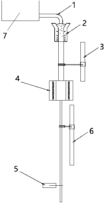
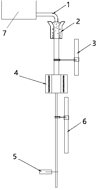
[0022] Example figure 1 shown. The device for manufacturing a preform for an optical element blank provided by the present invention includes a molding die 2 , a first drawing device 3 , a heating device 4 , a second drawing device 6 and a cutting device 5 . Wherein, the first drawing device 3 is located below the molding die 2, and the molding die 2 has a local cooling mechanism, a heating mechanism, and a temperature control device thereof, and the first drawing device 3 is equipped with a grip that can firmly hold the glass rod. device, power equipment and speed adjustment equipment, the molten glass is hardened and shaped into a solid round thick rod with a diameter of 25~45mm after passing through the mold. The heating device 4 is located below the first drawing device 3, and the heating elements of the heating device 4 are evenly distributed alo...


PUM

PropertyMeasurementUnit
diameteraaaaaaaaaa
diameteraaaaaaaaaa
diameteraaaaaaaaaa

Abstract

The invention relates to a manufacturing apparatus of a prefabricated rod for an optical element blank, and a method for manufacturing the element blank, and belongs to the technical field of opticalglasses. The problem of restriction of the shape of a raw material in the processing process of the optical element is mainly solved in the invention. The apparatus is mainly characterized in that theapparatus comprises a molding die, a first drawing device, a second drawing device, a heating device and a cutting device; the first drawing device is located below the molding device, and is used for molding glass to form a circular thick rod; the heating device is located below the first drawing device, and is used for heating and softening the circular thick rod; the second drawing device is located below the heating device, and is used for drawing the circular thick rod to form a circular thin rod; and the cutting device is located below the second drawing device, and is used for cuttingthe circular thin rod. The circular rod can be directly manufactured during manufacturing of the optical glass, and the shape of the cross section of the circular rod approaches the needed shape of the cross section of the optical element, so the circular rod can be directly sliced to manufacture the optical element blank.

Description

technical field [0001] The invention belongs to the technical field of optical glass, and in particular relates to a manufacturing device for an optical glass rod used for cutting blank sheets of optical elements and a method for manufacturing optical element blanks. Background technique [0002] There are two methods of manufacturing optical glass element blanks: the first method is the pressing method, the second method is the slicing method, the slicing method is to use glass sheets to make round rods through multiple processes, and then slice the round rods into element blanks . The molding method has great limitations. Many optical glasses containing rare earth components cannot be pressed once, and must be formed by secondary molding. The secondary molding process is complicated and the equipment is complicated, requiring a large number of operators. , it is difficult to reduce the manufacturing cost; the slicing method is a cold processing process, which is doubled c...

Claims


Application Information

Patent Timeline
Patent Type & Authority Applications(China)
IPC IPC(8): C03B15/14C03B23/047C03B33/06
Inventor 周希光王拓徐华峰徐光以寇小勇
Owner HUBEI NEW HUAGUANG NEW INFORMATION MATERIALS CO LTD
Learn More