Mass center self-calibration inertial flywheel device

An inertial flywheel and self-calibration technology, which is applied in the direction of measuring devices, machine/structural component testing, instruments, etc., can solve the problem of heavy transmission mass of small bevel gears and lead screws, automatic induction of uneven mass of flywheel discs, and small range of moment of inertia and other problems, to achieve the effect of reducing working vibration, wide application range and good practicability

Active Publication Date: 2019-05-03
HEFEI UNIV OF TECH
View PDF12 Cites 4 Cited by
  • Summary
  • Abstract
  • Description
  • Claims
  • Application Information

AI Technical Summary

Problems solved by technology

The flywheel of this device is vacantly sleeved on the flywheel shaft, and the flywheel can move a small amount of radial movement along the direction of the column against the action of the spring force, automatically sense the uneven quality of the flywheel, and automatically adjust the quality through the two-link mechanism and the connected quality adjustment block Unevenness, the mass distribution of the calibration flywheel, but the mass of the small bevel gear and the screw transmission is heavy, the mass of the mass block is light, and the range of the moment of inertia to be adjusted is small. At the same time, the automatic calibration of the center of mass position can only be calibrated in one direction, not in one direction. Calibration over the entire circumference of the flywheel

Method used


Image

  • Mass center self-calibration inertial flywheel device
  • Mass center self-calibration inertial flywheel device
  • Mass center self-calibration inertial flywheel device

Examples


Embodiment Construction

[0037] In order to make the purpose, technical solutions and advantages of the embodiments of the present invention clearer, the technical solutions in the embodiments of the present invention will be clearly and completely described below in conjunction with the embodiments of the present invention. Obviously, the described embodiments are part of the present invention Examples, not all examples. Based on the embodiments of the present invention, all other embodiments obtained by persons of ordinary skill in the art without creative efforts fall within the protection scope of the present invention.

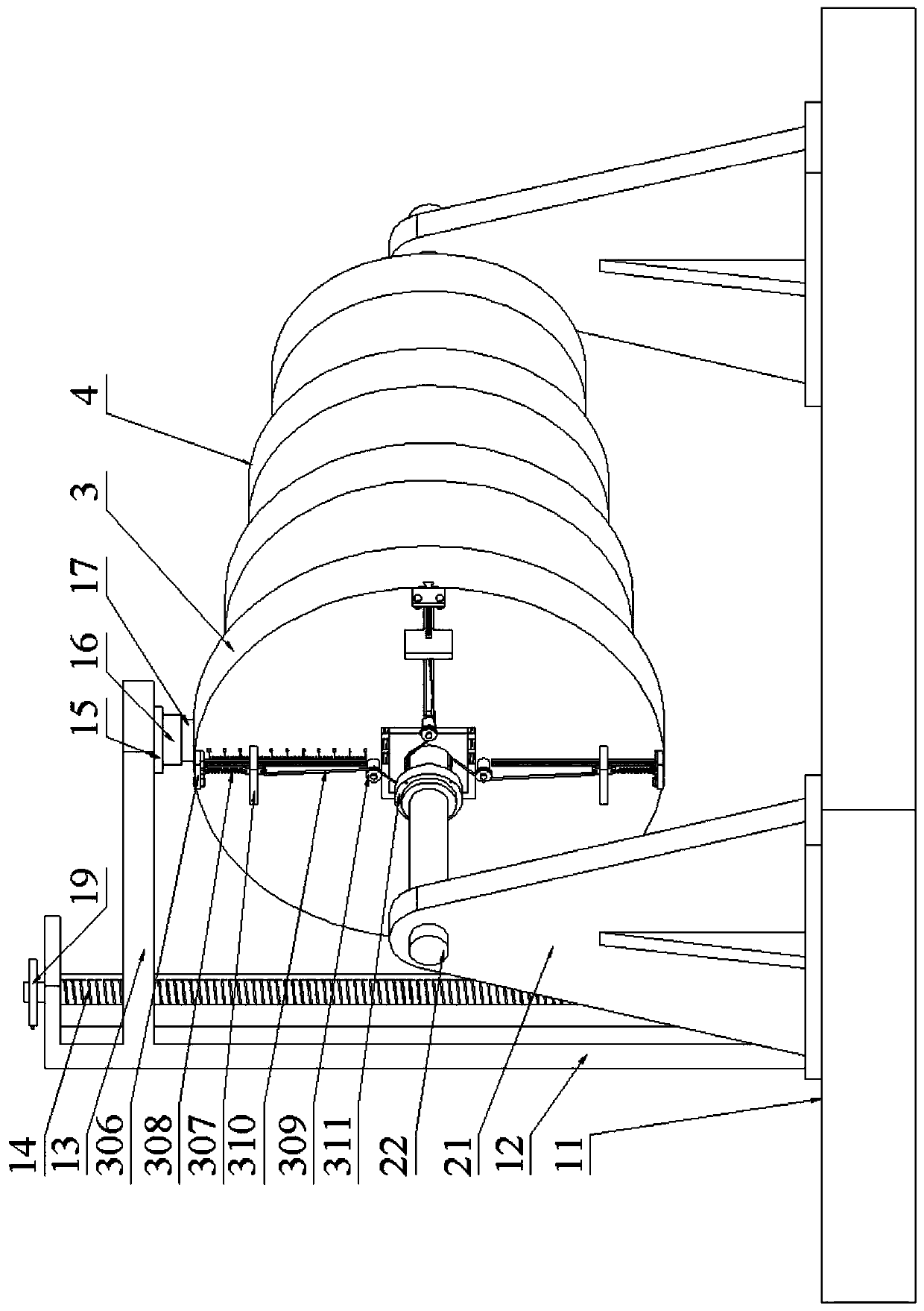
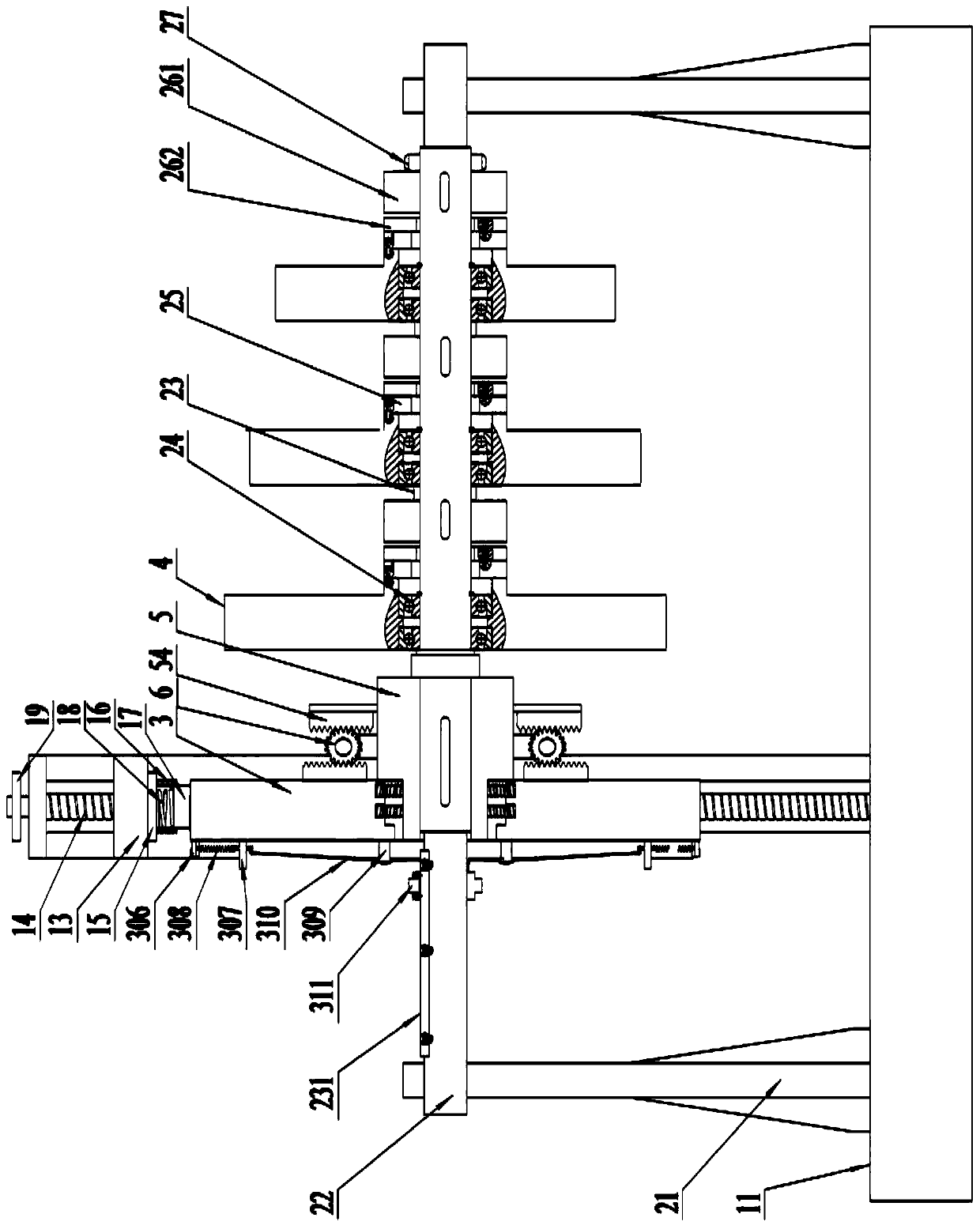
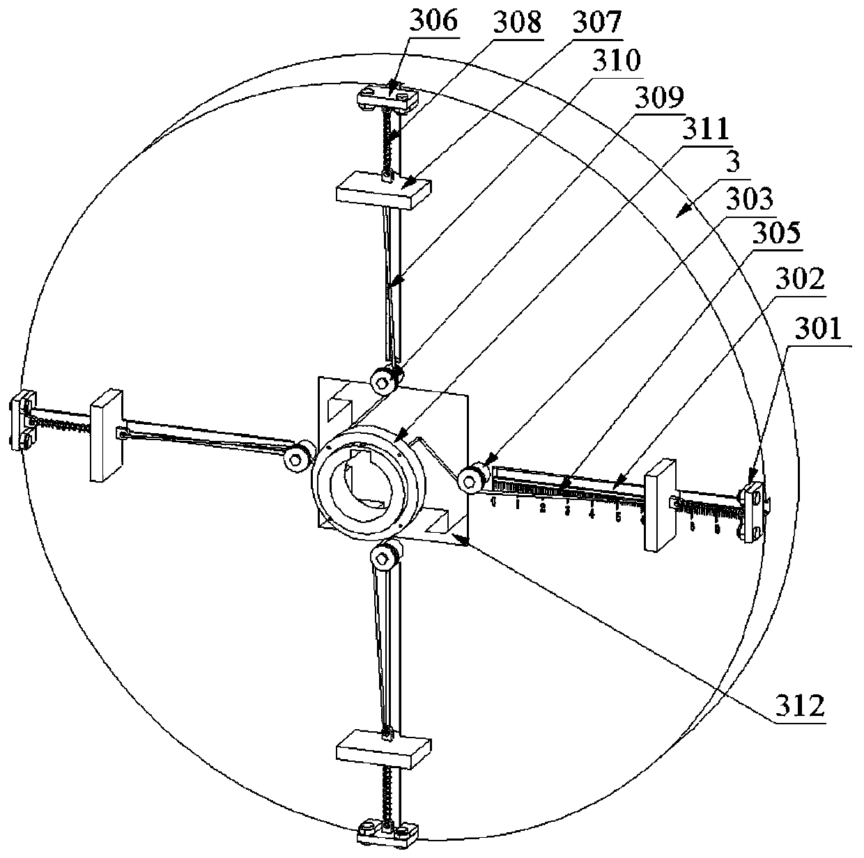
[0038] Such as Figure 1 to Figure 6 As shown, the structural relationship is as follows: a support frame 21 is provided on the base 11, a rotating shaft 22 is mounted on the support frame 21 for rotation, each cylindrical compression spring group is evenly arranged on the outer surface of one end of the boss assembly 5 along the circumferential direction, and the outer surface o...


PUM


Abstract

The invention discloses a mass center self-calibration inertial flywheel device, and relates to the technical field of experimental devices. Each cylindrical compression spring group is uniformly distributed at one end of the boss assembly in the circumferential direction, the outer side surface of the other end is circumferentially and uniformly provided with a plurality of groove upright posts,each support seat is arranged between each corresponding groove stand column and each corresponding cylindrical compression spring group, racks are fixedly arranged on the support base, gear assemblies are mounted on the support base, gears of the gear assemblies are respectively meshed with the racks, the boss assembly is in abutting fit with the mounting hole by means of each cylindrical compression spring set, a fixed flywheel disc rack is provided at the back of the fixed flywheel disc, and the fixed flywheel disc racks are respectively engaged with the gears. The fixed flywheel disc in rotation of the present invention can overcome the elastic force of the cylindrical compression spring in the corresponding direction to move along the axial direction of the positioning pin, the calibration of the position of the center of mass of the fixed flywheel disc is automatically realized, so that the center of mass of the fixed flywheel disc is collinear with the central axis of the rotating shaft, sliding and pulling the steel wire rope in the V-shaped groove by means of the sliding blocks, so as to adjust the rotational inertia of the fixed flywheel disc within a small range.

Description

technical field [0001] The invention relates to the technical field of experimental devices, in particular to an inertial flywheel device for simulating moment of inertia. Background technique [0002] The moment of inertia experiment is a common experiment in the laboratory. In various moment of inertia experimental devices, the flywheel is often used to simulate the moment of inertia due to its large mass and inertia radius. As far as the traditional simulation method is concerned, once the mass of the flywheel is fixed, the moment of inertia of the flywheel is also fixed. However, with the rapid development of modern technology, this simulation method with fixed moment of inertia can no longer meet the testing requirements of various mechanical equipment. More and more occasions require adjustable moment of inertia simulation device, and some even need to adjust the moment of inertia according to the load characteristics. The moment of inertia is adjusted in real time; i...

Claims


Application Information

Patent Timeline
Patent Type & Authority Applications(China)
IPC IPC(8): F16F15/315F16F15/36G01M1/10
Inventor 王道明罗洋均訾斌钱钧陈无畏邵文彬方时瑞
Owner HEFEI UNIV OF TECH
Why Eureka
Try Eureka