Dehumidifier

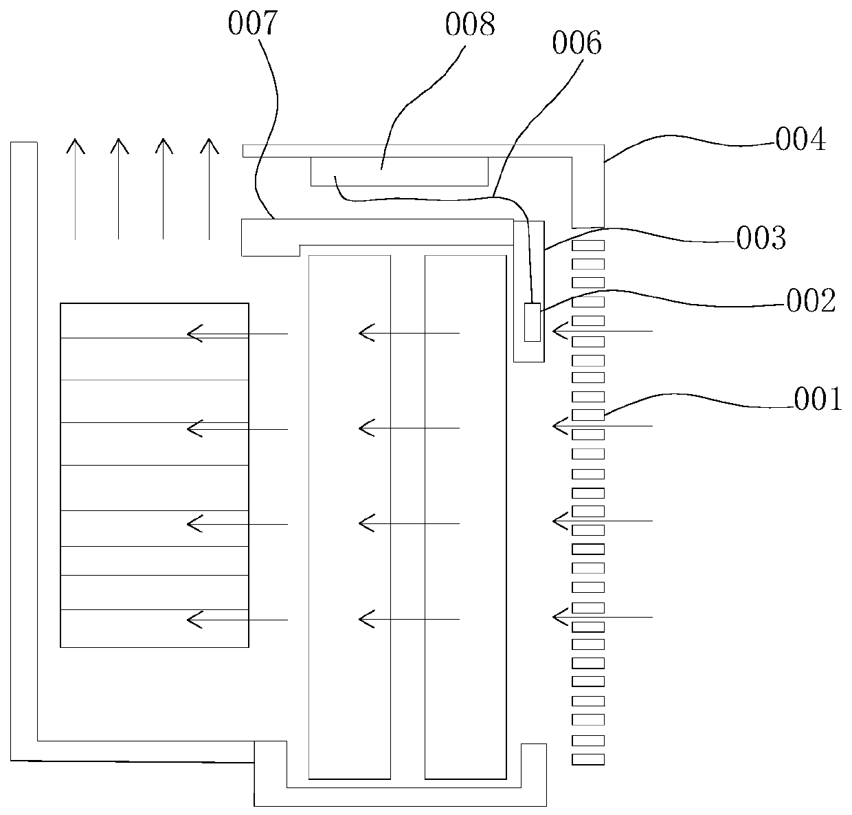
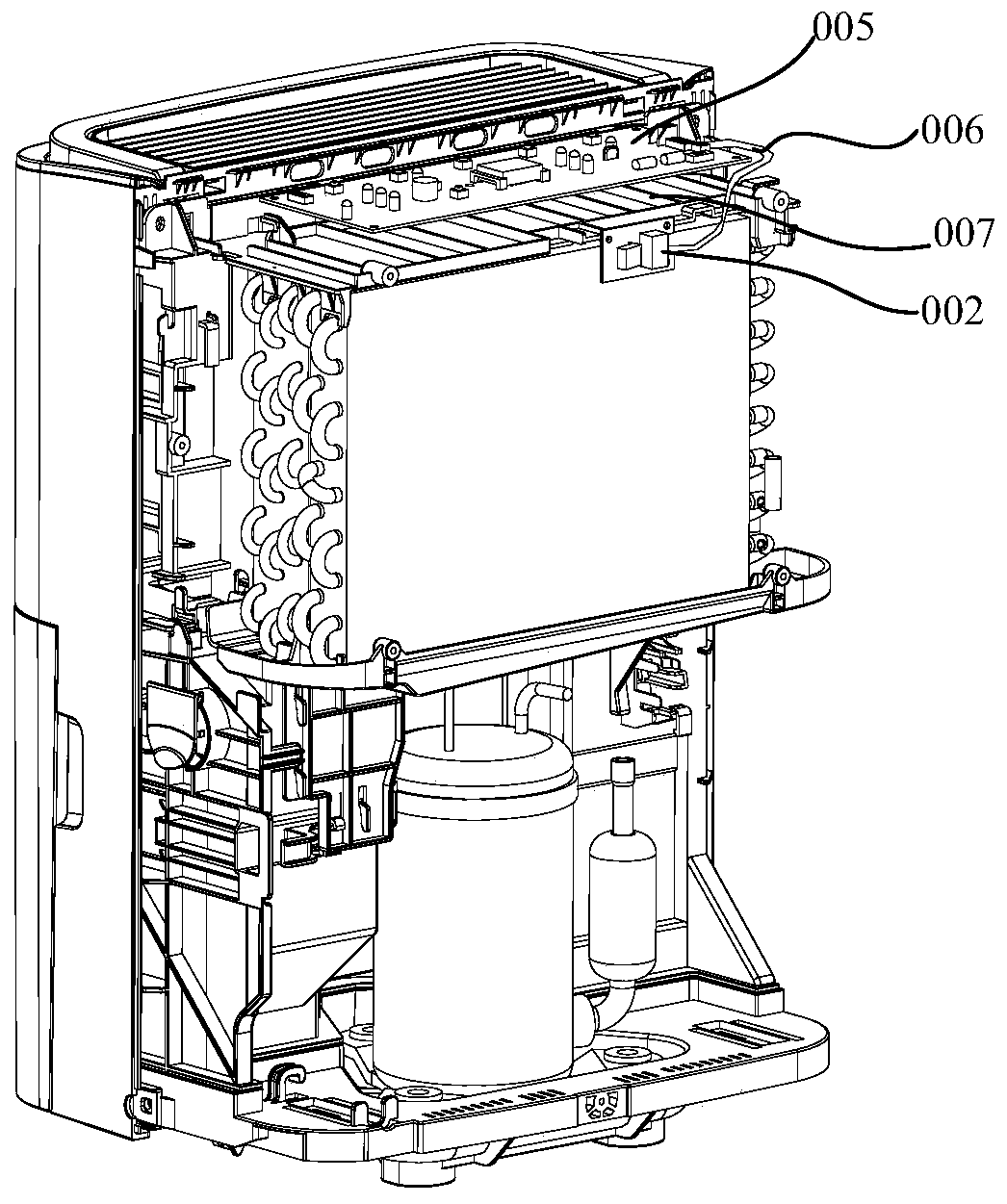
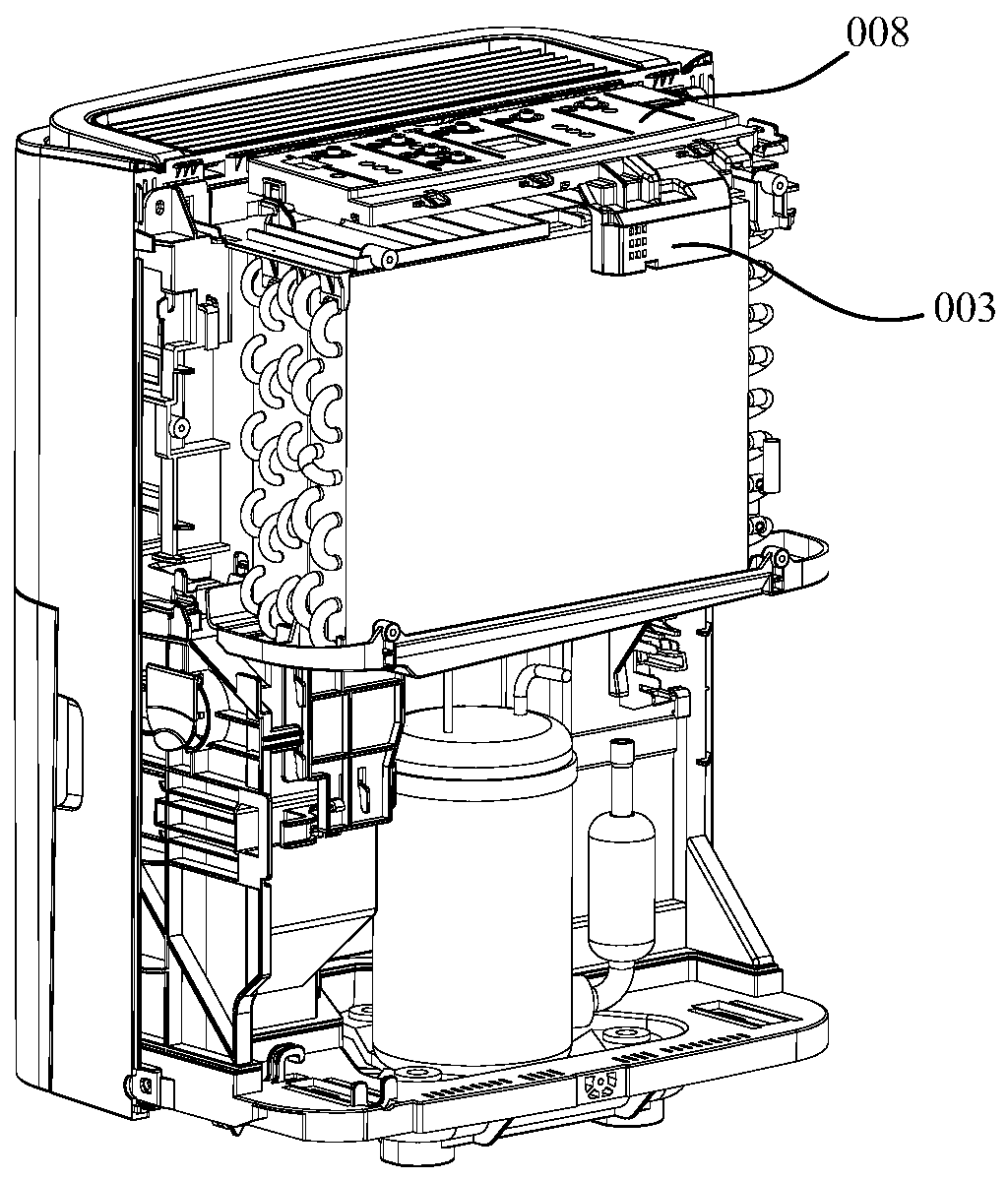
A technology for dehumidifiers and cabinets, which is applied in the field of air conditioning equipment, and can solve problems such as increased difficulty in sorting, difficulty in sorting connection lines 006, and inability of humidity sensor 002 to accurately measure the air humidity value, so as to avoid difficulties in connection lines and ensure dehumidification effect , the effect of ensuring accuracy

Active Publication Date: 2019-05-03
HISENSE (GUANGDONG) AIR CONDITIONER
View PDF9 Cites 1 Cited by
  • Summary
  • Abstract
  • Description
  • Claims
  • Application Information

AI Technical Summary

Problems solved by technology

At this time, it is also necessary to organize the connecting wire 006 to prevent the connecting wire 006 from being entangled with other electrical system connecting wires or interfering with other structures (interference means that the connecting wire 006 is in contact with other structures or even pressed by other structures). Assembly is nearing completion, by Figure 2 to Figure 4 It can be seen that the connection line 006 is located in a narrow space, and it becomes relatively difficult to arrange the connection line 006, which further increases the difficulty of arrangement
[0005] In order to reduce the difficulty of connecting wires, if the humidity sensor 002 is integrated on the main control board 005, the humidity sensor 002 will not be able to accurately measure the air humidity value, which will affect the dehumidification effect of the dehumidifier

Method used


Image

  • Dehumidifier
  • Dehumidifier
  • Dehumidifier

Examples


Embodiment Construction

[0030] The dehumidifier according to the embodiment of the present invention will be described in detail below with reference to the accompanying drawings.

[0031] In describing the present invention, it is to be understood that the terms "center", "upper", "lower", "front", "rear", "left", "right", "vertical", "horizontal", The orientations or positional relationships indicated by "top", "bottom", "inner", "outer", etc. are based on the orientations or positional relationships shown in the drawings, and are only for the convenience of describing the present invention and simplifying the description, rather than indicating or implying References to devices or elements must have a particular orientation, be constructed, and operate in a particular orientation and therefore should not be construed as limiting the invention.

[0032] The terms "first" and "second" are used for descriptive purposes only, and cannot be understood as indicating or implying relative importance or im...


PUM


Abstract

The invention discloses a dehumidifier, relates to the technical field of air conditioning equipment, and provides a dehumidifier to reduce the difficulty of assembly and disassembly under the premierof ensuring accurate measurement of the airflow parameters. The dehumidifier comprises a casing, wherein the casing is provided with an air inlet end and an air outlet end; an electric control deviceis arranged in the casing; the electric control device is provided with an electric control box, a controlling module, and a sensor module, wherein a wind path is arranged in the electric control box; an air intake port and an air outlet port are formed in the electric control box; the air intake port and the air outlet port communicate with the wind path; the air intake port is used to communicate with the air inlet end of the dehumidifier; the controlling module is arranged in the electric control box; the sensor module is positioned in the wind path and used for detecting the parameters ofthe airflow which enters into the wind path through the air intake port; and the obtained airflow parameters are transmitted to the controlling module, and the dehumidifier is controlled to operate through the controlling module. The assembly efficiency of the dehumidifier is improved and the manufacturing cost is reduced.

Description

technical field [0001] The invention relates to the technical field of air conditioning equipment, in particular to a dehumidifier. Background technique [0002] A dehumidifier is a kind of humid air that sucks in the indoor space, and makes the above humid air pass through a heat exchanger composed of a condenser and an evaporator flowing with refrigerant to reduce the humidity, and then discharges the dehumidified air to the indoor space again. , a device to reduce indoor humidity [0003] Existing a kind of dehumidifier, refer to figure 1 , the humidity sensing module 002 and the main control board 005 are two independent modules, and the humidity sensing module 002 and the main control board 005 are electrically connected through the connection line 006, wherein, in order to fully feel the humidity of the air to measure the humidity value For accurate measurement, the humidity sensor 002 is installed near the air intake grid 001 with better air flow, and installed in t...

Claims


Application Information

Patent Timeline
Patent Type & Authority Applications(China)
IPC IPC(8): F24F3/14F24F11/89F24F13/30F24F13/28F24F110/20F24F110/10
Inventor 梁炳祥谈裕辉韦小勤梁智文
Owner HISENSE (GUANGDONG) AIR CONDITIONER
Why Eureka
Try Eureka