

Oil removal cooling compressor
An oil cooling and air compressor technology, applied in the field of gas compression, can solve the problems of reducing the purity of compressed gas, the high risk of high-temperature gas, and the temperature rise of compressed gas, etc., and achieve reasonable structural design, low subjective dependence, and working accuracy high effect
- Summary
- Abstract
- Description
- Claims
- Application Information
AI Technical Summary
Problems solved by technology
Method used
Image

Examples
Embodiment Construction
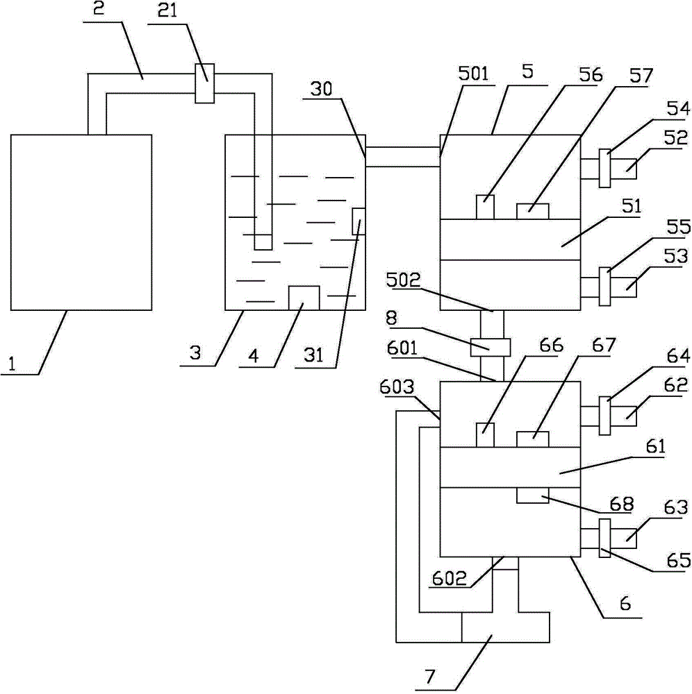
[0027] refer to figure 1 , a kind of deoiling cooling air compressor that the present invention proposes, comprises: cylinder 1, air supply pipeline 2, liquid storage tank 3, refrigeration device 4, first dehumidification box 5, second dehumidification box 6, three-way valve 7 and control module.
[0028] A gas compression device is arranged in the cylinder 1 for compressing gas. Cooling liquid is stored in the liquid storage tank 3, specifically, cooling water can be used. The refrigerating device 4 is installed in the liquid storage tank 3 and is located below the liquid surface for compensating the cooling capacity of the cooling liquid. The first end of the air supply pipe 2 is connected to the outlet of the cylinder 1, and the second end is inserted into the liquid storage tank 3 and is located below the liquid level. The liquid storage tank 3 is provided with an air outlet 301 and is located above the liquid level. The compressed gas output by the cylinder 1 enters th...
PUM
 Abstract
Description
Claims
Application Information