Dehumidification device of windowless underground storeroom

A storage room and dehumidification box technology, applied in the field of dehumidification, can solve the problems of long-term operation and high energy consumption

Inactive Publication Date: 2020-08-14
哈燕
View PDF1 Cites 1 Cited by
  • Summary
  • Abstract
  • Description
  • Claims
  • Application Information

AI Technical Summary

Problems solved by technology

However, each part of the device needs to be operated for a long time,

Method used


Image

  • Dehumidification device of windowless underground storeroom
  • Dehumidification device of windowless underground storeroom
  • Dehumidification device of windowless underground storeroom

Examples


Embodiment 1

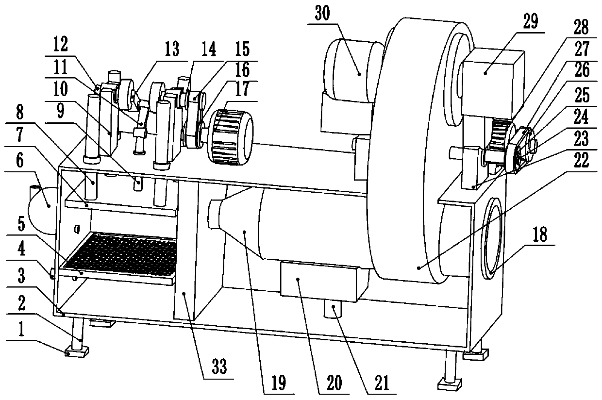
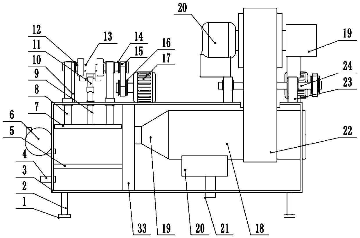
[0029] see Figure 1-5 , a dehumidification device for a windowless underground storage room, comprising a dehumidification box 3, the left and right sides of the lower surface of the dehumidification box 3 are provided with support legs 2, the lower end of the support legs 2 is provided with a pad 1, and the left side wall of the dehumidification box 3 The lower part is provided with a first drain port 4, and the middle part of the left side wall of the dehumidification box 3 is provided with an air pump 6. A filter plate 5 is provided between the walls, and a first drive motor 17 is provided on the upper left side of the dehumidification box 3. The output shaft of the first drive motor 17 is fixedly connected to the first pulley 16, and the first pulley 16 passes through the first belt 15. Connect the second pulley 14, the second pulley 14 is fixedly connected to the right end of the rotating shaft 12, the left side of the upper surface of the dehumidification box 3 is provi...

Embodiment 2

[0032] see figure 1 , the other content of this embodiment is the same as that of Embodiment 1, except that: the lower part of the dehumidification pipe 18 is provided with a water storage tank 20 , and the lower part of the water storage tank 20 is provided with a second drain port 21 . Because the air with higher humidity will encounter cold when passing through the dehumidification pipe 18, water droplets will adhere to the inner wall of the dehumidification pipe 18. At this time, a water storage tank 20 can be set at the bottom of the dehumidification pipe 18 to collect these water droplets, and pass through the second The drain port 21 discharges these water droplets to the outside of the device.

[0033] During the implementation of the present invention, when the humidity requirements for the storage room are low, only the air pump 6 can be started at this time, and the air pump 6 will suck the humid air in the storage room into the left side of the dehumidification box...


PUM


Abstract

The invention relates to the technical field of dehumidification. The invention discloses a dehumidification device of a windowless underground storeroom. The dehumidification device comprises a dehumidification box, a sucking pump is arranged in the middle of the left side wall of the dehumidification box, a first partition plate is arranged on the left side of the dehumidification box, a filterplate is arranged between the first partition plate and the left side wall of the dehumidification box, a first driving motor is arranged at the left upper part of the dehumidification box, an outputshaft of the first driving motor is fixedly connected with a first belt wheel which is connected with a second belt wheel through a first belt, the second belt wheel is fixedly connected with the right end of a rotating shaft, a crank is arranged in the middle of the rotating shaft, the middle of the crank is rotationally connected with the upper end of a supporting rod and a lower end of the supporting rod is rotationally connected with the upper end of a slide bar. According to the dehumidification device suitable for the windowless underground storeroom, the dynamic solid adsorption dehumidification function is achieved by arranging the dehumidification disc in the device, when the normal humidity requirement is low, only the sucking pump needs to be started, the first driving motor needs to be started intermittently, and energy consumption is low.

Description

technical field [0001] The invention relates to the technical field of dehumidification, in particular to a dehumidification device for a windowless underground storage room. Background technique [0002] The storage room refers to the inner space and the room adjacent to the house for the occupants to store daily necessities, production tools, grain and sundries. The living area of ​​modern people is limited, and the storage room is usually in the basement of the house. However, the storage room in the basement usually has no windows, the air circulation is not smooth, and it is accompanied by various problems such as humidity. Therefore, a device involving dehumidification is required. [0003] There are usually three methods of dehumidification: static solid adsorbent adsorption dehumidification method, refrigeration condensation dehumidification method and dynamic solid adsorption dehumidification method. Among them, the most economical, effective and suitable for large...

Claims


Application Information

Patent Timeline
IPC IPC(8): B01D53/26
CPCB01D53/261
Inventor 哈燕
Owner 哈燕
Why Eureka
Try Eureka