
Electronic expansion valve

An electronic expansion valve and rotor technology, applied in the direction of climate sustainability, high-efficiency regulation technology, mechanical equipment, etc., can solve the problems of increasing product trial production costs and increasing trial production costs, and achieve the goal of reducing trial production costs and product trial production costs Effect

Active Publication Date: 2021-12-07
ZHEJIANG DUNAN HETIAN METAL CO LTD
View PDF5 Cites 0 Cited by
  • Summary
  • Abstract
  • Description
  • Claims
  • Application Information

AI Technical Summary

Problems solved by technology

Since the rotor assembly in this structure (including the rotor connecting plate and the magnetic rotor) is directly welded and fixed to the screw, when the product has poor performance such as internal leakage and large flow deviation, the rotor assembly can only be scrapped, which increases the cost of product trial production ; In addition, the existing guide piece and the rotor connecting plate need to be welded and fixed, which further increases the cost of trial production

Method used


Image

  • Electronic expansion valve
  • Electronic expansion valve
  • Electronic expansion valve

Examples


Embodiment Construction

[0012] Hereinafter, embodiments of the present invention will be described in detail, but the present invention can be defined by the claims, and many different embodiments of cover.

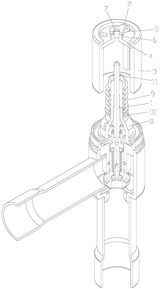
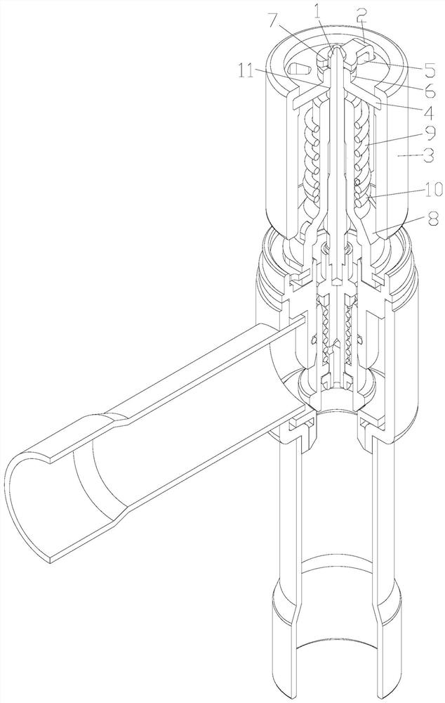
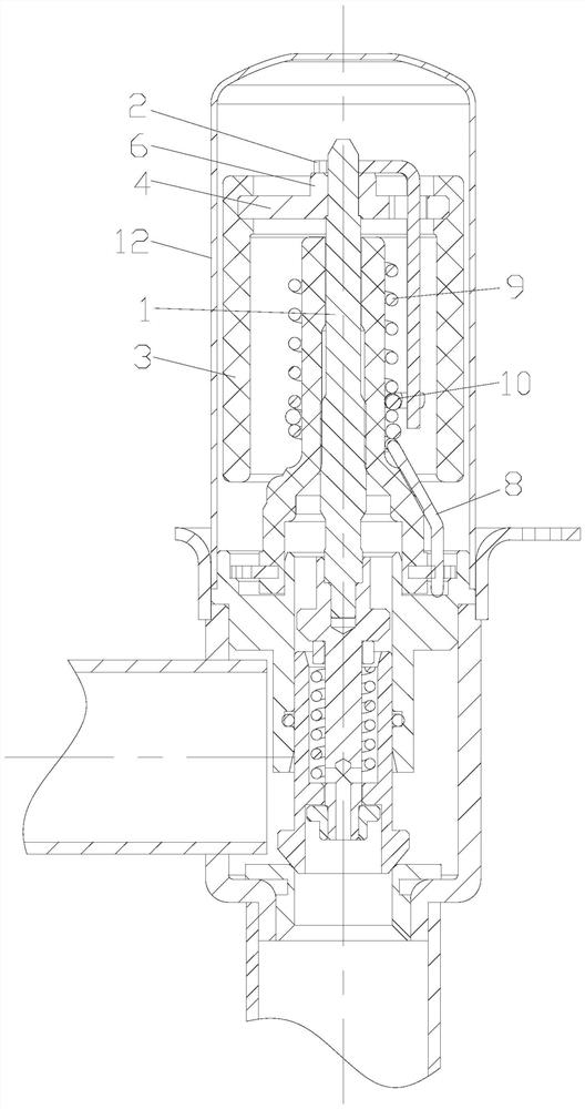
[0013] Please refer to Figure 1 to 5 Shown, according to an embodiment of the present invention, an electronic expansion valve including a rotor assembly, the screw 1 and the movable guide plate 2, the screw rotor provided in a sleeve assembly, the movable guide plate 2 is formed with a circumferential stop the rotor assembly, the movable guide plate 1 welded and fixed with the screw 2, the rotor assembly 2 by turning the movable plate drive screw 1 rotates.

[0014] Electronic expansion valve of the present invention, the movable guide plate 2 is formed with a circumferential stop the rotor assembly and the movable guide plate 2 and the screw 1 is no direct relationship between the welding is welded and fixed, and the rotor assembly and the rotor assembly by turning the movable plate 2 the drive sc...


PUM


Abstract

The invention provides an electronic expansion valve. The electronic expansion valve includes a rotor assembly, a screw (1) and a guide piece (2). The rotor assembly is sleeved outside the screw (1), and the guide piece (2) forms a circumferential limit with the rotor assembly. The guide piece ( 2) It is welded and fixed to the screw rod (1), and the rotor assembly drives the screw rod (1) to rotate through the guide piece (2). According to the electronic expansion valve of the present invention, the cost of product trial production can be reduced, and the utilization rate of product components can be improved.

Description

Technical field [0001] The present invention relates to the field of refrigeration and air conditioning technology, in particular, it relates to an electronic expansion valve. Background technique [0002] Conventional valve head from the balance structure of the electronic expansion valve, which member comprises a rotor magnet rotor, rotor webs, guiding the movable piece, the movable guide plate provided on the rotor and the rotor web and the stepped stopper secured web; the expansion valve assembly when the first product is determined by the rotation of the screw set to zero, then the rotor is sleeved on the screw member, rotation of the rotor and the movable member so that the guide plate and stopper ring contacts the stopper, the screw and the rotor web assembly by laser welding etc. fixedly connected. Since the rotor assembly of the structure (the connecting plate and the magnet rotor comprises a rotor) directly soldered fixedly connected with the screw, so that when the pro...

Claims


Application Information

Patent Timeline
Patent Type & Authority Patents(China)
IPC IPC(8): F25B41/34
CPCY02B30/70
Inventor 詹少军詹钱勇侯晓炜
Owner ZHEJIANG DUNAN HETIAN METAL CO LTD
Learn More