
Parameterized glovebox damper arrangement method

An arrangement method and glove box technology, applied in the field of glove boxes, can solve the problems of damper quality risk, cost increase, design uncertainty, etc., and achieve the effects of shortening the design cycle, improving work efficiency, and reducing trial production costs.

Pending Publication Date: 2022-01-04
DONGFENG MOTOR GRP
View PDF0 Cites 0 Cited by
  • Summary
  • Abstract
  • Description
  • Claims
  • Application Information

AI Technical Summary

Problems solved by technology

[0002] The glove box is an important functional part of the interior, and its opening time is a very important indicator of perceived quality. Although the opening time of the glove box has a target definition, there is no damper arrangement technology based on the opening time of the glove box
Due to the damper arrangement technology without the opening time of the glove box, it is impossible to determine whether the opening time of the glove box meets the requirements in the structural design and CNC sample verification stages, which brings design uncertainty. Determinism, which leads to the need to modify the damper if the opening time of the glove box cannot meet the requirements during the trial production and loading stage. Modifying the damper will cause the damper to be unusable, which will increase the cost and increase the quality of the damper. Risk; if the damper is not modified, the glove box body needs to be modified, which also increases the manufacturing cost; if the modification of the damper and the glove box body cannot meet the project requirements, it is necessary to make concessions to reduce the perception of the glove box quality

Method used


Image

  • Parameterized glovebox damper arrangement method
  • Parameterized glovebox damper arrangement method
  • Parameterized glovebox damper arrangement method

Examples


Embodiment Construction

[0040] In order to make the object, technical solution and advantages of the present invention clearer, the present invention will be further described in detail below in conjunction with the accompanying drawings and embodiments. It should be understood that the specific embodiments described here are only used to explain the present invention, not to limit the present invention. In addition, the technical features involved in the various embodiments of the present invention described below can be combined with each other as long as they do not constitute a conflict with each other.

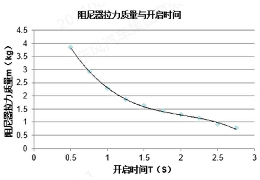
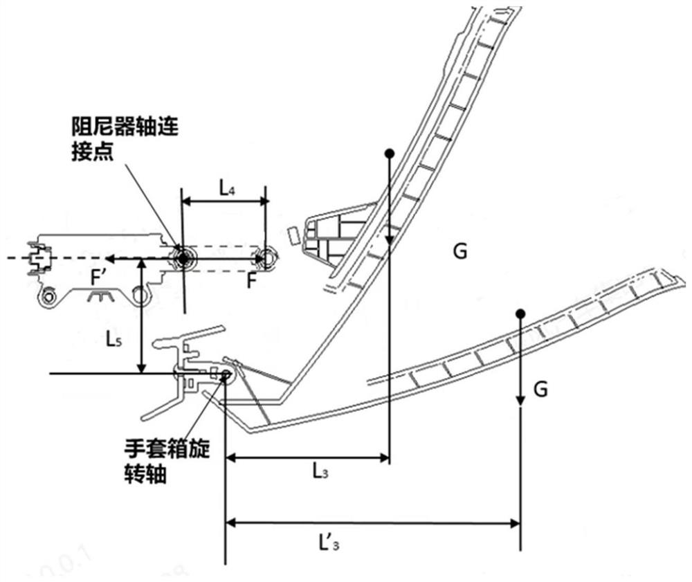
[0041] figure 2 It is the motion schematic diagram of the glove box damper of the present invention and the relationship diagram between the tension mass of the damper and the opening time, wherein the relationship between the tension mass of the damper and the opening time is tested by a physical test, and the test frequency exceeds 10,000 times, and then passed Fitting the data yields

[00...


PUM


Abstract

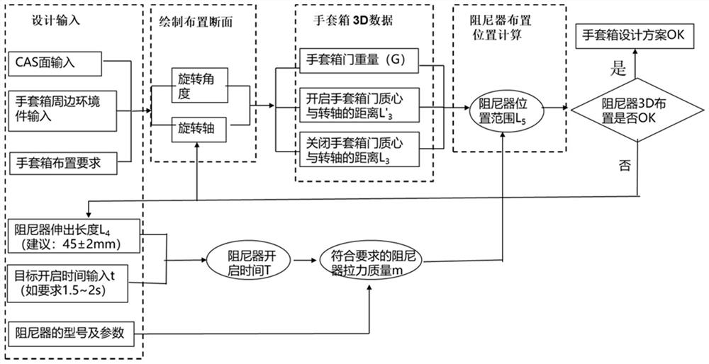
The invention discloses a parameterized glovebox damper arrangement method which comprises the steps of inputting basic data of a glovebox and a damper, wherein the basic data at least comprise CAS surface parameters, glovebox surrounding environment parameters, glovebox arrangement requirements, damper extension length, target opening time t, damper models and corresponding parameters; drawing a section for arranging the damper, wherein drawing parameters of the section at least comprise a rotation angle and a rotation axis; generating 3D data of the glovebox according to the basic data of the glovebox, wherein the 3D data of the glove box at least comprises the weight G of a glovebox door, the distance between the mass center of the glovebox door and the rotating shaft is L'3 when the glovebox door is completely opened, and the distance between the mass center of the glovebox door and the rotating shaft is L3 when the glovebox door is closed; generating the damper opening time T and the damper counterweight mass m according to the basic data of the damper; and calculating to obtain a damper arrangement position range L5. According to the invention, the arrangement position of the glovebox damper can be accurately and rapidly positioned, the design period is shortened, and the manufacturing risk is reduced.

Description

technical field [0001] The invention belongs to the field of glove boxes, and in particular relates to a parameterized glove box damper arrangement method. Background technique [0002] The glove box is an important functional part of the interior, and its opening time is a very important indicator of perceived quality. Although the glove box opening time has a target definition, there is no damper arrangement technology based on the glove box opening time. Due to the damper arrangement technology without the opening time of the glove box, it is impossible to determine whether the opening time of the glove box meets the requirements in the structural design and CNC sample verification stages, which brings design uncertainty. Determinism, which leads to the need to modify the damper if the opening time of the glove box cannot meet the requirements during the trial production and loading stage. Modifying the damper will cause the damper to be unusable, which will increase the ...

Claims


Application Information

Patent Timeline
Patent Type & Authority Applications(China)
IPC IPC(8): G06F30/15G06F30/20G06F119/14
CPCG06F30/15G06F30/20G06F2119/14
Inventor 李威王君丽杜左五王洪明梁海明
Owner DONGFENG MOTOR GRP
Learn More