Water injection system, ice machine and refrigerator

A water injection system and refrigerator technology, applied in ice making, ice making, household refrigeration equipment, etc., can solve the problem of inaccurate water addition in the ice making box, avoid adding too much or too little water, and facilitate the process of adding water Effect

Pending Publication Date: 2019-05-03
HAIER SMART HOME CO LTD
View PDF9 Cites 4 Cited by
  • Summary
  • Abstract
  • Description
  • Claims
  • Application Information

AI Technical Summary

Problems solved by technology

[0004] In order to solve the problem of inaccurate water addition in the ice box in the prior art, the o

Method used


Image

  • Water injection system, ice machine and refrigerator
  • Water injection system, ice machine and refrigerator
  • Water injection system, ice machine and refrigerator

Examples


Embodiment 1

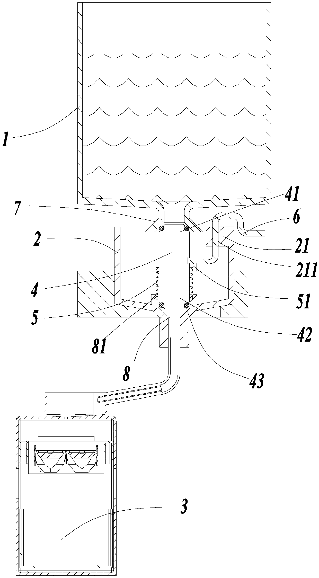
[0028] An embodiment of the present invention provides a water injection system, such as figure 1 with figure 2 As shown, it includes a water storage part 1 and a water demand part 3, the water storage part 1 is used to hold water or an external water source, and the water demand part 3 is used to receive water from the water storage part 1;

[0029] The water injection system also includes a quantitative part 2, a water valve 4, a holder 5 and a trigger 6. The quantitative part 2 is connected to the water storage part 1 through the water inlet 7, and the quantitative part 2 is connected to the water demand part 3 through the water outlet 8. In this embodiment The water inlet 7 is arranged at the bottom of the water storage part 1, and the water outlet 8 is arranged at the bottom of the quantitative part 2. Water flows into the quantitative part 2 from the water inlet 7 at the bottom of the water storage part 1 by its own gravity, and then flows into the quantitative part 2 f...

Embodiment 2

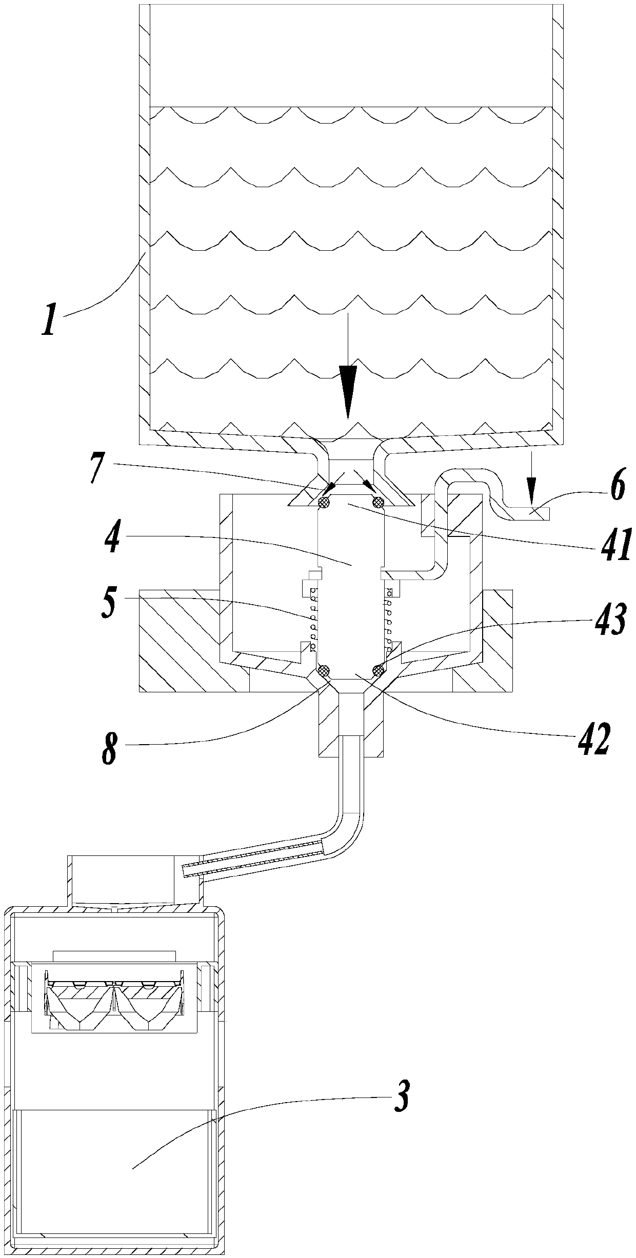
[0046] ginseng Figure 4 with Figure 5 Another embodiment is provided, and the same reference numerals used in this embodiment as in Embodiment 1 mean structures / components with similar or identical features. The difference between this embodiment and embodiment 1 lies in: the shapes of the water inlet 7 , the water outlet 8 , the first blocking body and the second blocking body; and the setting position of the quantitative part 2 . This difference will be introduced in detail below, and other parts that are the same as those in Embodiment 1 will not be repeated here.

[0047] In this embodiment, the water inlet 7 and the water outlet 8 are both set as step-shaped openings, and the first baffle body 41 and the second baffle body 42 are also respectively set as baffles matching the shapes of the corresponding water inlet 7 and water outlet 8. body; such as image 3 shown. Of course, the water inlet 7 and the first baffle body are set to match in shape, the water outlet 8 a...


PUM


Abstract

The invention discloses a water injection system, an ice machine and a refrigerator. The water injection system comprises a water storage part, a water needing part, a quantification part, a water valve, a holding part and a trigger part; the quantification part communicates with the water storage part through a water inlet, the quantification part communicates with the water needing part througha water outlet, the water valve is movably arranged between the water inlet and the water outlet, and is provided with a first position capable of opening the water outlet while the water inlet is closed and a second position capable of closing the water outlet while the water inlet is opened, the holding part controls the water valve to be at the first position, and the trigger part drives the water valve to move to the second position. Through the quantification part, the water valve is controlled to the opened and closed through the holding part and the trigger part, the water valve controls the water storage part to be closed and the water needing part to be opened at the same time or the water storage part to be opened and the water needing part to be closed at the same time, the amount of water flowing in the quantification part is constant, the amount of water flowing into the water needing part from the water storage part is constant, the problem of adding of too much or littlewater can be solved, and the water adding process is facilitated.

Description

technical field [0001] The invention relates to a water injection system, in particular to an ice maker and a refrigerator with the water injection system. Background technique [0002] At present, the ice making box is usually placed in the refrigerator to make ice, but filling the ice making box with water has always been a difficult point in the ice making system. The current existing scheme is to place the ice making box in the freezing chamber, and add water to the ice making box from the outside, which eliminates the inconvenience of water splashing inside when the ice making box is put into the refrigerator. [0003] At present, in the process of adding water to the ice making box, a certain amount of water flows into the ice making box by connecting an external water source and configuring a sensor and a solenoid valve, but the cost is high, and when adding water manually, the amount of water added cannot be accurate Control, there is a problem that too little water...

Claims


Application Information

Patent Timeline
IPC IPC(8): F25C1/24F25D23/12
Inventor 崔船张延庆薛建军阳军左立华杜启海
Owner HAIER SMART HOME CO LTD
Why Eureka
Try Eureka