
Method and device for arranging deformation monitoring identifier

A marking and deformation technology, applied in the direction of measuring devices, measuring point marks, instruments, etc., can solve problems such as inappropriate spatial positions

Inactive Publication Date: 2019-05-03
INST OF ROCK AND SOIL MECHANICS - CHINESE ACAD OF SCI
View PDF6 Cites 2 Cited by
  • Summary
  • Abstract
  • Description
  • Claims
  • Application Information

AI Technical Summary

Problems solved by technology

[0004] The purpose of the embodiments of the present invention is to provide a method and device for quickly laying out surface deformation monitoring points based on a nail shooter, which solves the need to wait for the construction period required for concrete pouring, unsuitable spatial positions, and avoid possible problems in the process of embedding monitoring points. Dangerous areas and other problems, so as to achieve the purpose of fast and reliable buried monitoring points to meet the surface deformation monitoring requirements of emergency projects

Method used


Image

  • Method and device for arranging deformation monitoring identifier
  • Method and device for arranging deformation monitoring identifier
  • Method and device for arranging deformation monitoring identifier

Examples


Embodiment Construction

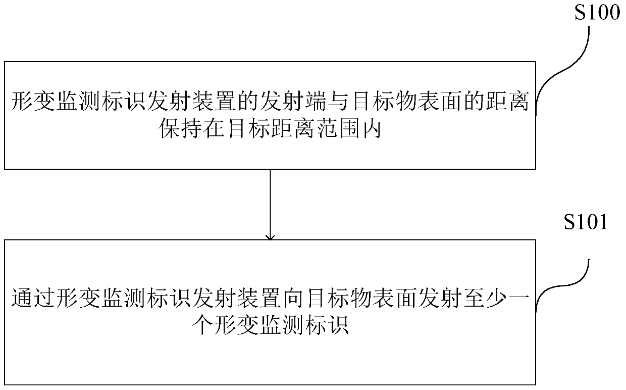
[0032] figure 1 For a schematic flowchart of a method for laying out deformation monitoring marks provided by an embodiment of the present invention, see figure 1 , the method includes:

[0033] Step S100 , keeping the distance between the transmitting end of the deformation monitoring mark transmitting device and the surface of the target object within the target distance range.

[0034] Step S101 , transmitting at least one deformation monitoring mark to the surface of the target through the deformation monitoring mark emitting device.

[0035] Specifically, the deformation monitoring mark is used to be fixed on the surface of the object, and when the surface of the object is deformed, it is monitored to obtain deformation information.

[0036] The embodiment of the present invention provides a method for laying out deformation monitoring marks, which transmits the deformation monitoring marks into the monitoring object by operating the transmitting device, so as to realiz...


PUM

PropertyMeasurementUnit
Thicknessaaaaaaaaaa
Widthaaaaaaaaaa
Depthaaaaaaaaaa

Abstract

The invention, which relates to the field of civil engineering safety monitoring, provides a method and device for arranging a deformation monitoring identifier. The method comprises the following steps that: a distance between a transmitting end of a deformation monitoring identifier transmitting device and the surface of a target object is kept to be within a target distance range; and at leastone deformation monitoring identifier is transmitted to the target surface by the deformation monitoring identifier transmitting device, wherein the deformation monitoring identifier is fixed on the target surface and is monitored to obtain deformation information when the target surface deforms. According to the invention, the operation becomes convenient; the portability is high; and the time and effort are saved. A nail shooting device is provided with an energy source, so that field working becomes convenient; the method has the safe and reliable fastening effect; and the method and devicecan be applied to monitoring objects with different hardness values, like a soil layer, a brickwork, concrete, and the steel.

Description

technical field [0001] Embodiments of the present invention relate to the field of civil engineering safety monitoring, and in particular, relate to a method and device for arranging deformation monitoring signs. Background technique [0002] Due to the occurrence of civil engineering construction or geological disasters, the engineering structure and geotechnical body will be disturbed, and when the deformation reaches a certain level, the safety of the engineering structure and the surrounding environment will be endangered. Therefore, safety monitoring must be carried out to ensure the safety of protected objects. [0003] For the deformation monitoring of some emergency projects, it is necessary to bury monitoring points safely, quickly and conveniently, so as to carry out monitoring in time and evaluate the safety of the project. However, the embedment of conventional monitoring points is often difficult to meet the needs of emergency projects. For example, the pit (ho...

Claims


Application Information

Patent Timeline
IPC IPC(8): G01B21/32G01C15/02
Inventor 覃卫民王浩王成汤谢壁婷陈舞
Owner INST OF ROCK AND SOIL MECHANICS - CHINESE ACAD OF SCI
Learn More